A Long-Range Meshtastic Relay

In the past few years we’ve seen the rise of low-power mesh networking devices for everything from IoT devices, weather stations, and even off-grid communications networks. These radio modules are largely exempt from licensing requirements due to their low power and typically only operate within a very small area. But by borrowing some ideas from the licensed side of amateur radio, [Peter Fairlie] built this Meshtastic repeater which can greatly extend the range of his low-power system.

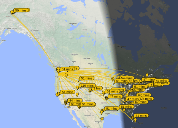
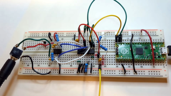
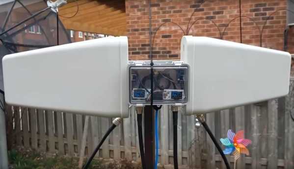
[Peter] is calling this a “long lines relay” after old AT&T microwave technology, but it is essentially two Heltec modules set up to operate as Meshtastic nodes, where one can operate as a receiver while the other re-transmits the received signal. Each is connected to a log-periodic antenna to greatly increase the range of the repeater along the direction of the antenna. These antennas are highly directional, but they allow [Peter] to connect to Meshtastic networks in the semi-distant city of Toronto which he otherwise wouldn’t be able to hear.

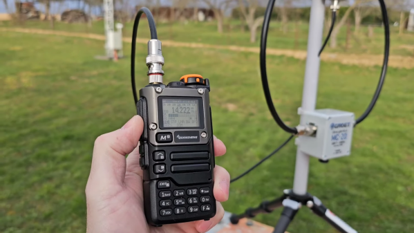
With the two modules connected to the antennas and enclosed in a weatherproof box, the system was mounted on a radio tower allowing a greatly increased range for these low-power devices. If you’re familiar with LoRa but not Meshtastic, it’s become somewhat popular lately for being a straightforward tool for setting up low-power networks for various tasks. [Jonathan Bennett] explored it in much more detail as an emergency communications mode after a tornado hit his home town.

Continue reading “A Long-Range Meshtastic Relay”

A Practical Guide To Understanding How Radios Work

How may radios do you own? Forget the AM/FM, GMRS/FRS radios you listen to or communicate with. We’re talking about the multiple radios and antennas in your phone, your TV, your car, your garage door opener, every computing device you own- you get the idea. It’s doubtful that you can accurately count them even in your own home. But what principles of the electromagnetic spectrum allow radio to work, and how do antenna design, modulation, and mixing affect it? [Michał Zalewski] aka [lcamtuf] aims to inform you with his excellent article Radios, how do they work?

A simple illustration compares a capacitor to a dipole antenna.

For those of you with a penchant for difficult maths, there’s some good old formulae published in the article that’ll help you understand the physics of radio. For the rest of us, there are a plethora of fantastic illustrations showing some of the less obvious principals, such as why a longer diploe is more directional than a shorter dipole.

The article opens with a thought experiment, explaining how two dipole antennas are like capacitors, but then also explains how they are different, and why a 1/4 wave dipole saves the day. Of course it doesn’t stop there. [lcamtuf]’s animations show the action of a sine wave on a 1/4 wave dipole, bringing a nearly imaginary concept right into the real world, helping us visualize one of the most basic concepts of radio.

Now that you’re got a basic understanding of how radios work, why not Listen to Jupiter with your own homebrew receiver?

How Much Bandwidth Does CW Really Occupy?

Amateur radio license exams typically have a question about the bandwidths taken up by various modulation types. The concept behind the question is pretty obvious — as guardians of the spectrum, operators really should know how much space each emission type occupies. As a result, the budding ham is left knowing that continuous wave (CW) signals take up a mere 150 Hertz of precious bandwidth.

But is that really the case? And what does the bandwidth of a CW signal even mean, anyway? To understand that, we turn to [Alan (W2AEW)] and his in-depth look at CW bandwidth. But first, one needs to see that CW signals are a bit special. To send Morse code, the transmitter is not generating a tone for the dits and dahs and modulating a carrier wave, rather, the “naked” carrier is just being turned on and off by the operator using the transmitter’s keyer. The audio tone you hear results from mixing the carrier wave with the output of a separate oscillator in the receiver to create a beat frequency in the audio range.

That seems to suggest that CW signals occupy zero bandwidth since no information is modulated onto the carrier. But as [Alan] explains, the action of keying the transmitter imposes a low-frequency square wave on the carrier, so the occupied bandwidth of the signal depends on how fast the operator is sending, as well as the RF rise and fall time. His demonstration starts with a signal generator modulating a 14 MHz RF signal with a simple square wave at a 50% duty cycle. By controlling the keying frequency, he mimics different code speeds from 15 to 40 words per minute, and his fancy scope measures the occupied bandwidth at each speed. He’s also able to change the rise and fall time of the square wave, which turns out to have a huge effect on bandwidth; the faster the rise-fall, the larger the bandwidth.

It’s a surprising result given the stock “150 Hertz” answer on the license exam; in fact, none of the scenarios [Allen] tested came close to that canonical figure. It’s another great example of the subtle but important details of radio that [Alan] specializes in explaining.

Continue reading “How Much Bandwidth Does CW Really Occupy?”

LoRA, With No Radio

A LoRa project has traditionally required a dedicated radio module, because it’s a commercially licenced protocol. But as the way it works has been progressively reverse engineered, it’s become ever more possible to produce a LoRA radio for yourself. But what about a LoRA radio without a radio at all? [CNLohr] has managed just that, by driving a microcontroller pin and relying on one of its harmonics to provide enough RF to be received by a LoRA gateway.

The video below the break goes into the process in great detail, revealing some of the tricks. Undersampling to create intentional aliasing for example allows subharmonic peaks to be produced in unexpected places. Most of the development is performed on Espressif microcontrollers, but as the code is optimised it becomes possible to use it on much more modest silicon. The dirt cheap CH32V003 RISC-V microcontroller for example can be a LoRA transmitter able to talk to a gateway at a range of hundreds of metres with the CH32 and 2.5km with the ESP32. The code can be found in this GitHub repository.

The CH32 can’t receive of course, and it relies on barfing harmonics all over the spectrum to work. But on the other hand its total RF output is so tiny that we’re guessing a filter for the LoRA band might even make it almost legal. He’s got a little way to go before beating the record though.

Continue reading “LoRA, With No Radio”

Automatic Position Reporting Over HF Radio

While most of us carry cell phones that have GPS and other location services, they require a significant amount of infrastructure to be useful. Drive from Washington to Alaska like [Lonney] did a while back, where that infrastructure is essentially nonexistent, and you’ll need to come up with some other solutions to let friends and family know where you are.

A tool called the Automatic Packet Reporting System (APRS) is fairly robust in the very high frequency (VHF) part of the amateur radio spectrum, but this solution still relies on a not-insignificant amount of infrastructure for the limited distances involved with VHF. [Lonney] adapted a few other tools to get APRS up and running in the HF range, letting his friends keep tabs on him even from the most remote locations.

Continue reading “Automatic Position Reporting Over HF Radio”

Open HT Surgery Gives Cheap Transceiver All-Band Capabilities

Watch out, Baofeng; there’s a new kid on the cheap handy talkie market, and judging by this hardware and firmware upgrade to the Quansheng UV-K5, the radio’s hackability is going to keep amateur radio operators busy for quite a while.

Like the ubiquitous Baofeng line of cheap transceivers, the Quansheng UV-K5 is designed to be a dual-band portable for hams to use on the 2-meter VHF and 70-centimeter UHF bands. While certainly a useful capability, these bands are usually quite range-limited, and generally require fixed repeaters to cover a decent geographic area. For long-range comms you want to be on the high-frequency (HF) bands, and you want modulations other than the FM-only offered by most of the cheap HT radios.

Luckily, there’s a fix for both problems, as [Paul (OM0ET)] outlines in the video below. It’s a two-step process that starts with installing a hardware kit to replace the radio’s stock receiver chip with the much more capable Si4732. The kit includes the chip mounted on a small PCB, a new RF choke, and a bunch of nearly invisible capacitors. The mods are straightforward but would certainly benefit from the help of a microscope, and perhaps a little hot air rework. Once the hardware is installed and the new firmware flashed, you have an HT that can receive signals down to the 20-meter band, with AM and SSB modulations, and a completely redesigned display with all kinds of goodies.

It’s important to note that this is a receive-only modification — you won’t be transmitting on the HF bands with this thing. However, it appears that the firmware allows you to switch back and forth between HF receive and VHF/UHF transceive, so the radio’s stock functionality is still there if you need it. But at $30 for the radio and $12 for the kit, who cares? Having a portable HF receiver could be pretty handy in some situations. This looks like yet another fun hack for this radio; we’ve seen a few recently, including a firmware-only band expansion and even a Trojan that adds a waterfall display and a game of Pong. Continue reading “Open HT Surgery Gives Cheap Transceiver All-Band Capabilities”

Breadboard SDR Doesn’t Need Much

[Grug Huhler] built a simple Tayloe mixer and detector on a breadboard. He decided to extend it a bit to be a full-blown software defined radio (SDR). He then used WSJT-X to monitor FT8 signals and found that he could pick up signals from all over the world with the little breadboard system.

A Raspberry Pi Pico generates a quadrature clock that acts as the local oscillator for the radio. All the processing of the input signal to a quadrature signal is done with a 74LV4052A, which is nothing more than an analog multiplexer. In principle, the device takes a binary number from zero to three and uses it to connect a common signal to one of four channels. There are two common lines and two sets of four channels. In this case, only half of the chip is in use.

An antenna network (two resistors and a capacitor) couples the antenna to one of the common pins, and the Pi generates two square waves, 90 degrees out of phase with each other. This produces select signals in binary of 00, 01, 11, and 10. An op amp and a handful of passive components couple the resulting signals to a PC soundcard, where the software processes the data. The Pi can create clocks up to about 15 or 20 MHz easily using the PIO.

The antenna is a 20-meter-long wire outside, and that accounts for some of the radio’s success. There are several programs than can work with soundcard input like this and [Grug] shows Quisk as a general-purpose receiver. If you missed the first video explaining the Tayloe mixer design, you can catch it below the first video.

This isn’t the first breadboard SDR we’ve seen, but they all use different parts. We’ve even seen a one-bit SDR with three components total (not including the microcontroller). Seriously.

Continue reading “Breadboard SDR Doesn’t Need Much”