The Best-Sounding Walnut You’ll Hear Today

Do you ever find yourself eating walnuts and think, this would make a great enclosure for something like a Bluetooth speaker? That seems to be exactly what happened to [Penguin DIY].

In the mesmerizing video after the break, you’ll see [Penguin DIY] do what seems to be impossible. They start with a tiny 5 V power bank module which is still not small enough to fit, so they remove all the components and dead-bug them back together.

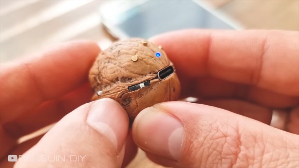
This is really just the beginning. There of course has to be a female USB of some type, so [Penguin DIY] Dremels out the perfect little slot for it.

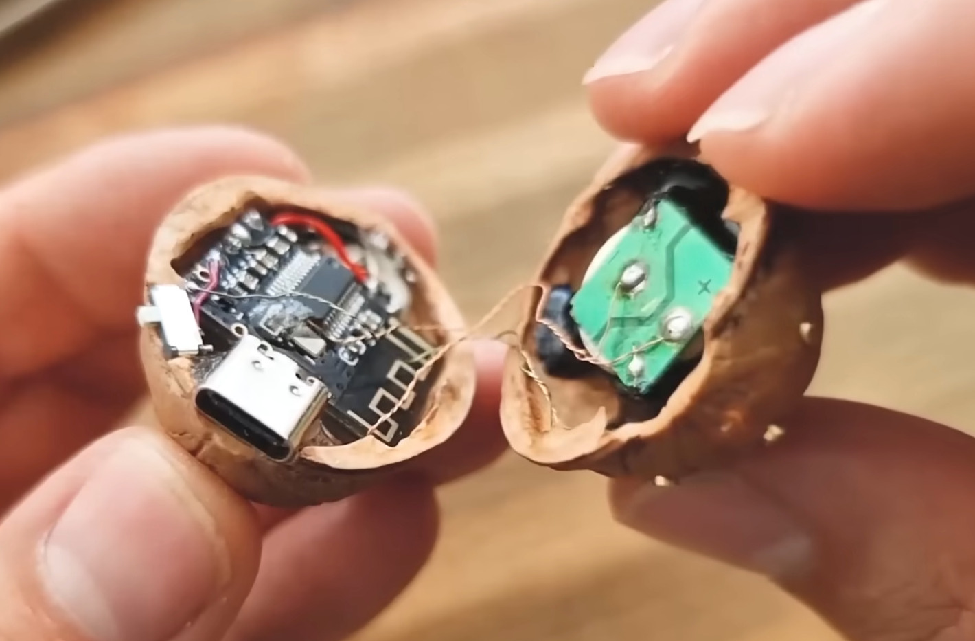
They did manage to stack and fit a MH-MH18 Bluetooth audio module and an HXJ8002 mini audio amplifier module in the walnut, but of course, it took a lot of fiddly wiring to extend the LEDs and wire them up.

Then in the other half of the shell went the 4Ω 2 W mini speaker. [Penguin DIY] of course drilled a ton of little holes in the shell for the sound to come through. Also on this side are three tiny switches for play/pause and previous and next track, and the latter two can be long pressed to control the volume. Definitely check this out after the break.

Do the notifications of your Bluetooth speaker annoy you? There’s a hack for that.

Continue reading “The Best-Sounding Walnut You’ll Hear Today”

A wall clock made from wires and electronic components

Form Follows Function In This Circuit Sculpture Clock

Electronic components are strictly functional objects: their appearance is determined by the function they’re meant to fulfil. But that doesn’t mean there’s no beauty in them. In fact, a whole discipline called circuit sculpture exists that aims to make beautiful shapes out of nothing more than electronic components and wires. Today we can show you [Maarten Tromp]’s latest work in this field: a wall-mounted clock that he’s christened the Clock Sculpture.

The clock’s main structure consists of two concentric rings made from galvanized steel wire, held together by twelve spokes. All components are soldered directly onto those two rings, with no additional mechanical support. Steel isn’t the greatest material for soldering to, but [Maarten] managed to make it work with a high-wattage soldering iron and a bit of plumbers’ flux.

The overall design is simple but clever: the outer ring holds 60 LEDs to indicate the minutes, with every fifth LED always illuminated dimly in order to provide a background reference in dark conditions. There are 24 LEDs on the inner ring to indicate the twelve hours as well as the “half-hours” in between. Without these, the dial would look a bit odd at 30 minutes past the hour.

Detail of a circuit sculpture clockA mains transformer, plus a single diode, a buffer capacitor and a 7805 regulator form a simple DC power supply, with its negative terminal connected to the steel frame. Time is kept by an ATtiny13A that counts mains frequency pulses. There’s no way to adjust the time: you’ll have to plug in the clock exactly at noon or midnight in order to synchronize it with the outside world. A crude method perhaps, but one that fits well with the clock’s bare-bones aesthetic.

The individual LEDs are driven by a set of twelve 74HC595 shift registers, all mounted dead-bug style between the two rings. Signals and power are carried between the chips by inconspicuous grey wires taken from old IDE cables; this gives the clock a clean, uncluttered appearance. [Maarten] has had the sculpture clock in his office for several months and while it apparently took some time to get used to, he claims it’s easy to read in bright and dark conditions.

Circuit sculpture has formed the basis for several stunning clock projects: this Tie Fighter-shaped clock for instance, or this insanely complex LED clock. Our 2020 Circuit Sculpture contest yielded many breathtaking designs, too.

Scribble Your Way To Quick Printed Circuit Boards

There are a variety of techniques employed by electronic constructors seeking the convenience of a printed circuit board without the inconvenience of making a printed circuit board. Dead bug style construction in which the components float on a spiders-web of soldered leads above a ground plane is one, Manhattan style construction in which pads made from small cut squares of bare copper-clad PCB are glued on top of a groundplane is another.

[Freestate QRP] has another take on this type of electronics, with what he calls “Scribble style” construction. He cuts away copper from bare board to create pads and rudimentary tracks, and for him the magic ingredient comes from his choice of an engineer’s scribe to do the job. This is where the “scribble” comes from, creating a pad is as simple as drawing it with the scribe.

Of course, this technique is not entirely new, constructors have been doing this type of work for years with Dremel tools, hand engraving tools, and similar. If you’ve ever tried to do it with a knife or scalpel you will know that it’s hardly an easy task with those hand tools so the prospect of another one doing a better job is rather interesting. He’s ready and able to demonstrate it in action, showing us a couple of RF circuits using the technique.

Have you tried this technique, or one like it? How did you get on, tell us in the comments. Meanwhile, you might like to read our own [Dan Maloney]’s look at dead bug and Manhattan construction.

Non-standard circuit boards

Non-standard Circuits: Jazz For Electrons

How creative are you when you make your circuit boards? Do you hunt around for different materials to use for the board? As long as it’s an insulator and can handle the heat of a soldering iron, then anything’s fair game. Or do you use a board at all? Let’s explore some options, both old favorites and some you may not have seen before, and see if we can get our creative juices flowing.

Transparent Circuit Boards

Let’s start with the desire to show more circuit and less board. For that we can start with [CNLohr]’s circuits on glass, usually microscope slides. What’s especially nice about his is that he provides detailed videos of the whole process, including all the failed things he tried along the way. Since he didn’t start with copper clad board, he instead glued his copper sheet to the glass using Loctite 3301. That was followed by the usual etching process, though with plenty of gotchas along the way.

In the end, he made a number of circuits, including an LED clock with the LEDs on the glass itself, and even attempted leading the community in making a glass keytar. The latter didn’t work out, but the resulting glass circuits are a work of art anyway.

What about making a transparent circuit board out of acrylic? [Frank Zhao] attempted just that by laser cutting troughs into the acrylic for the traces, and then drawing in nickel ink. But something in the ink ate into the acrylic, and as if that wasn’t bad enough, the voltage drop across the nickel was too high for his circuit. Suggestions were made in the comments for how to solve these problems, but unless we missed it, we haven’t seen another attempt yet.

But we’ve only just begun. What if you wanted even more transparency?

Continue reading “Non-standard Circuits: Jazz For Electrons”

A Deadbugged GPS/GLONASS/Geiger Counter

So you think you’re pretty good at soldering really tiny parts onto a PCB? You’re probably not as good as [Shibata] who made a GPS/GLONASS and Geiger counter mashup deadbug-style with tiny 0402-sized parts.

The device uses an extremely small GPS/GLONASS receiver, an AVR ATxmega128D3 microcontroller, a standard Nokia phone display and an interesting Geiger tube with a mica window to track its location and the current level of radiation. The idea behind this project isn’t really that remarkable; the astonishing thing is the way this project is put together. It’s held together with either skill or prayer, with tiny bits of magnet wire replacing what would normally be PCB traces, and individual components making up the entire circuit.

While there isn’t much detail on what’s actually going on in this mess of solder, hot glue, and wire, the circuit is certainly interesting. Somehow, [Shibata] is generating the high voltage for the Geiger tube and has come up with a really great way of displaying all the relevant information on the display. It’s a great project that approaches masterpiece territory with some crazy soldering skills.

Thanks [Danny] for sending this one in.

Continue reading “A Deadbugged GPS/GLONASS/Geiger Counter”