A Solar-Powered Point-and-Shoot, Circa 1961

Try to put yourself in the place of an engineer tasked with building a camera in 1961. Your specs include making it easy to operate, giving it automatic exposure control, and, oh yeah — you can’t use batteries. How on Earth do you accomplish that? With a very clever mechanism powered by light, as it turns out.

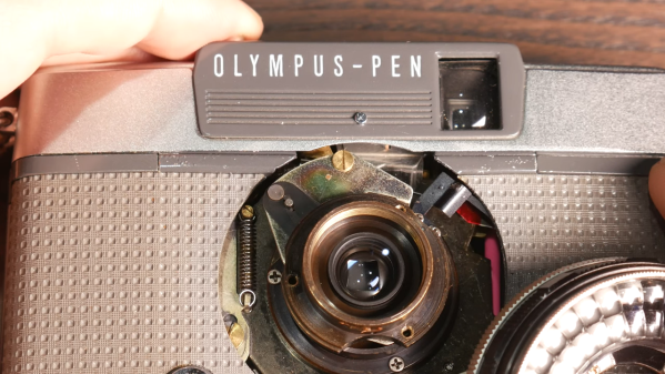
This one comes to us from [Alec Watson] over at Technology Connections on YouTube, which is a channel you really need to check out if you enjoy diving into the minutiae of the mundane. The camera in question is an Olympus Pen EES-2, which was the Japanese company’s attempt at making a mass-market 35-mm camera. To say that the camera is “solar-powered” is a bit of a stretch, as [Alec] admits — the film advance and shutter mechanism are strictly mechanical, relying on springs and things to power them. It’s all pretty standard camera stuff.

But the exposure controls are where this camera gets interesting. The lens is surrounded by a ring-shaped selenium photocell, the voltage output of which depends on the amount of light in the scene you’re photographing. That voltage drives a moving-coil meter, which waggles a needle back and forth. A series of levers and cams reads the position of the needle, which determines how far the lens aperture is allowed to open. A clever two-step cam allows the camera to use two different shutter speeds, and there’s even a mechanism to prevent exposure if there’s just not enough light. And what about that cool split-frame exposure system?

For a camera with no electronics per se, it does an impressive job of automating nearly everything. And [Alec] does a great job of making it interesting, too, as he has in the past with a deep-dive into toasters, copy protection circa 1980, and his take on jukebox heroics.

Continue reading “A Solar-Powered Point-and-Shoot, Circa 1961”

Old Scanner Finds New Life In DIY PCB Fab

Cheap, high-quality PCBs are truly a wonder of our age. That a professionally fabricated board with silkscreen and solder mask can be ordered online and delivered to your door has lowered the bar between a hobbyist project and a polished product. But the wait can be agonizing, and it can throw a wrench into the iterative design process. What to do?

[Andras Kabai] knows the answer to that, and this former flatbed scanner turned into a UV exposer is the centerpiece of his DIY board fab. The old Mustek scanner was a couple of bucks secondhand, and provided not only the perfect form-factor for a board scanner but a trove of valuable parts to reuse. [Andras] replaced the original fluorescent light bar with a long, narrow PCB stuffed with UV LEDs, and added an Arduino Mega to control the original stepper drive. The project looks like it went through a little feature creep, with an elaborate menu system and profiles that include controls for exposure time, the brightness of the LED array via PWM, and the length of board that gets exposed. It’s clearly a work in progress, but early results are encouraging and we’ll be watching to see how [Andras]’ in-house fab shapes up.

This approach to PCB fab is only one of many, of course. You can turn a budget 3D-printer into a PCB machine, or even use an LCD to mask the boards during exposure. The latter intrigues us — an LCD mask and a scanning UV light source could make for a powerful PCB creation tool.

F/stop Printer For Analog Printing Black And White Photos

This beautifully crafted device is a timer used for getting the perfect exposure when making film prints of photos. But in addition to keeping time, it also does logarithmic calculations that are based on the f-stop values used for each exposure. It does this in 1/100th of a stop increments. While he was at it, [William] also decided to pack in a bunch of other features like dry down correction, and support for making test strips. This is a little hard to understand when discussed in the abstract, but just take a look at his video after the break where [William] walks us through an example exposure and all will become clear.

You can see from the construction page that the device is basically an Arduino shield. It provides a relay for controlling the exposure lamp, a keypad, rotary encoder, and character LCD. Slap it in a fancy case, connect it to the equipment you’re using, and you’ll be creating perfect prints in no time flat!

Continue reading “F/stop Printer For Analog Printing Black And White Photos”

Tri-rotor Helicopter With Full Autopilot

Quadcopters stand aside, here’s a three-rotor helicopter we think you’re going to love. The body is made out of plywood and carbon fiber rods, keeping it light enough to be easily lifted by just 3 motors while making sure the force doesn’t tear the aircraft apart. Three gyroscopes, two accelerometers, three magnetometers, and a GPS module are all used in conjunction for an autopilot system. There’s a lot of great pictures and videos but our favorite, embedded after the break, shows the tricopter writing messages in the sky using light and camera exposure tricks similar to this ground-based trike.

Continue reading “Tri-rotor Helicopter With Full Autopilot”

Single LED Ultraviolet Exposure Box

[Jacques Lebrac] built a UV exposure box for printed circuit boards using just one LED. He usually makes boards that are just a few square inches and didn’t think building a box that had upwards of 80 LEDs was worth his time. He passed by the low power LEDs for a single 5W unit. Pumping 1.5A through this LED makes for some quick exposures, but causes heat issues. To solve this, an aluminum arm was used to mount the LED, acting as mechanical support and heat sink at the same time. The voltage regulator was glued directly to the chassis, providing at least some heat dissipation.

[Jacques] came up with an eloquent solution for holding the transparency and copper clad in place. A piece of acrylic is hinged on the back using a piece of aluminum tubing. The front has a magnet glued to it, with another one in the base to hold the cover tight to the work surface during operation.

Building A UV Exposure Box

There are two methods of using etchant resist when making circuit boards. We use the toner transfer method that requires ironing on laser toner to the copper, but you can also use chemical resist that reacts to ultraviolet light. [Bogdan] decided to start doing more of the latter so he built a UV exposure box to make the process easier.

It is possible to use flourescent light bulbs for this, but he decided to use UV LEDs, a method we’ve also seen before. But there’s always room to innovate, and [Bogdan] built-in a couple of nice features that are new to us. Because the UV light can be bad for your eyes, he included a set of red visible-light LEDs on the bottom half of the box that are used to align two layers of exposure mask when making double-sided boards. There’s also a switch that automatically shuts off the UV light when the box is opened. And as the coup-de-grace, he added a programmable timer to regulate the exposure, using his newly created box when etching the PCB for it.

Beer Can Pinhole Camera

When [Justin Quinnell] sent in his beer can pinhole camera, we were just floored. The parts are easy to obtain, and the process for building and ‘shooting’ with the camera are near effortless.

The really impressive part of this hack is letting your camera sit for 6 months facing the sun. Yes, you read that correct, a 6 month exposure. Check out after the break for one of his astonishing shots, and trust us, its well worth the click. Continue reading “Beer Can Pinhole Camera”