Wandering Through Old Word Processors Yields A Beast

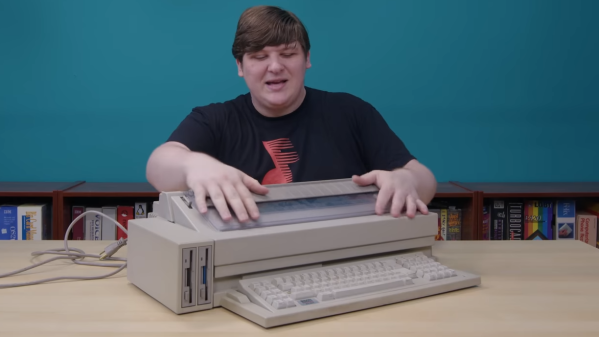
The world once ran on hardcopy, and when the digital age started to bring new tools and ways of doing things, documents were ripe for change. Today, word processors and digital documents are so ubiquitous that they are hardly worth a thought, but that didn’t happen all at once. [Cathode Ray Dude] has a soft spot for old word processors and the journey they took over decades, and he walks through the Olivetti ETV 2700.

In the days of character displays and no multitasking, WYSIWYG as a concept was still a long ways off.

The ETV 2700 is a monstrous machine; a fusion of old-school word processor, x86-based hardware, and electric 17 inch-wide typewriter.

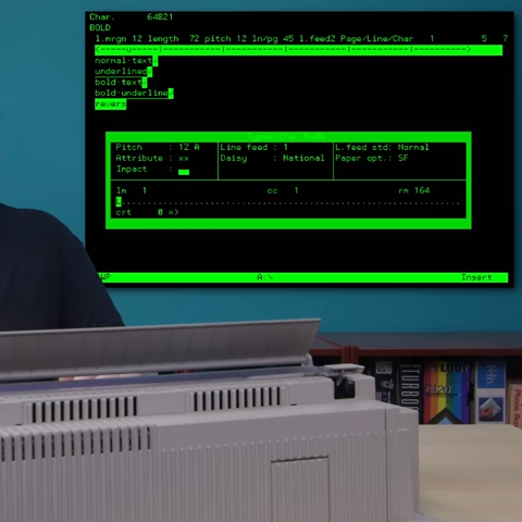
With it one could boot up a word processor that is nothing like the WYSIWYG of today, write and edit a document, and upon command, the typewriter portion could electronically type out a page. A bit like a printer, but it really is an electric typewriter with a computer interface. Characters were hammered out one at a time with daisy wheel and ink ribbon on a manually-loaded page using all the usual typewriter controls.

While internally the machine has an x86 processor, expects a monitor and even boots MS-DOS, the keyboard had its own layout (and even proprietary keys and functions), did not support graphical output, and in other ways was unusual even by the standards of the oddball decades during which designers and products experimented with figuring out what worked best in terms of functionality and usability.

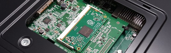
Nowadays, we see AI-enabled typewriter projects and porting vintage OSes to vintage word processor hardware, but such projects are in some part possible in part thanks to the durability of these devices. The entire video is embedded below, but you can jump directly to what the Olivetti ETV 2700 looked like on the inside if that’s what interests you most.

Continue reading “Wandering Through Old Word Processors Yields A Beast”

The Regulatory Side Of Rolling Your Own Moderate Solar Farm

[Russell Graves] lives in Idaho and recently connected his solar installation to the grid, which meant adhering to regulatory requirements for both the National Electric Code (NEC) as well as complying with the local power company’s own regulations. His blog post is an interesting look at the whole regulatory process and experience, and is of interest to anyone curious about running their own solar farm, whether they have plans to connect it to the grid or not.

A circuit breaker that met NEC code, but not the power company’s requirements.

The power company has a very different set of priorities from the NEC, and part of [Russell]’s experience was in having to meet requirements that weren’t documented in the expected places, so study of the materials didn’t cut it. In particular, the power company needed the system to have disconnects with conductors that visually move out of position when disconnected. [Russell] was using NEC-compliant circuit breakers that met NEC code, but they didn’t meet the power company requirement for conductors that can be visually confirmed as being physically disconnected. Facing a deadline, [Russell] managed to finesse a compliant system that was approved, and everything got signed off just as winter hit.

How well does his solar farm work out? Sometimes the panels produce a lot of power, sometimes nearly nothing, but it has been up and running for all of winter and into spring. Over the winter, [Russell] pulled a total of 3.1 MWh from the grid, mainly because his home is heated with electric power. But once spring hit, he started pushing considerably more into the grid than he was pulling; on some days his setup produces around 95 kWh, of which about 70 kWh gets exported.

[Russell] didn’t go straight to setting up his own modest solar farm; we saw how he began by making his own ideal of a perfect off-grid office shed that ran on solar power, but it has certainly evolved since then and we’re delighted to see that he’s been documenting every bit of the journey.

This Week In Security: Bluetooth Hacking, NEC Phones, And Malicious Tor Nodes

One of the fun things about vulnerability research is that there are so many places for bugs to hide. Modern devices have multiple processors, bits of radio hardware, and millions of lines of code. When [Veronica Kovah] of Dark Mentor LLC decided to start vulnerability research on the Bluetooth Low Energy protocol, she opted to target the link layer itself, rather than the code stack running as part of the main OS. What’s interesting is that the link layer has to process data before any authentication is performed, so if a vulnerability is found here, it’s guaranteed to be pre-authentication. Also of interest, many different devices are likely to share the same BLE chipset, meaning these vulnerabilities will show up on many different devices. [Veronica] shares some great info on how to get started, as well as the details on the vulnerabilities she found, in the PDF whitepaper. (Just a quick note, this link isn’t to the raw PDF, but pulls up a GitHub PDF viewer.) There is also a video presentation of the findings, if that’s more your speed.

The first vuln we’ll look at is CVE-2019-15948, which affects a handful of Texas Instruments BT/BLE chips. The problem is in how BLE advertisement packets are handled. An advertisement packet should always contain a data length of at least six bytes, which is reserved for the sending device address. Part of the packet parsing process is to subtract six from the packet length and do a memcpy using that value as the length. A malicious packet can have a length of less than six, and the result is that the copy length integer underflows, becoming a large value, and overwriting the current stack. To actually turn this into an exploit, a pair of data packets are sent repeatedly, to put malicious code in the place where program execution will jump to.

The second vulnerability of note, CVE-2020-15531 targets a Silicon Labs BLE chip, and uses malformed extended advertisement packets to trigger a buffer overflow. Specifically, the sent message is longer than the specification says it should be. Rather than drop this malformed message, the chip’s firmware processes it, which triggers a buffer overflow. Going a step further, this chip has non-volatile firmware, and it’s possible to modify that firmware permanently. [Veronica] points out that even embedded chips like these should have some sort of secure boot implementation, to prevent these sort of persistent attacks.
Continue reading “This Week In Security: Bluetooth Hacking, NEC Phones, And Malicious Tor Nodes”

A Win For The Raspberry Pi Compute Module

News comes from the Raspberry Pi Foundation, of something of a coup for their Compute Module product. Support for it is to be integrated into NEC’s line of commercial displays, and the electronics giant has lined up a list of software partners to provide integrated signage solutions for the platform.

It is interesting to note how NEC have done this, while it’s being spun by the Foundation as a coup for them the compute module sits on a daughter board in a slot on the back of the display rather than on the display PCB itself. They are likely hedging their bets with this move, future daughter boards could be created to provide support for other platforms should the Compute Module board fail to gain traction.

Given that this relates to a high-end commercial product from just one manufacturer, what’s in it for us in the hardware community? After all, it’s not as if you’ll be seeing Compute Module slots in the back of domestic TVs or monitors from NEC or any other manufacturer in the near future. The answer is that such a high-profile customer lends the module platform a commercial credibility that it may not yet have achieved.  Until now, it has found a home mainly in more niche or boutique products, this appearance in something from a global manufacturer takes it to a new level. And as the module finds its way into more devices the chances of them coming within the reach of our community and providing us with opportunities for adapting them for our purposes through the Pi platform become ever greater.

The use of the Compute Module in displays made for public signage is oddly a continuation of an unseen tradition for ARM-based machines from Cambridge. Aside from British schools a significant market for the Acorn Archimedes platform that spawned ARM was the embedded signage market, and even today there are still plenty of signs concealing RiscOS machines out there in the wild.

We covered the launch of the Compute Module in 2014, but it’s fair to say it’s not appeared much since in the world of Raspberry Pi projects from hardware hackers. This is not because it’s not a good platform; more likely that the Raspberry Pi models A, B, and particularly the Zero are so much cheaper when you consider the significant cost of the Compute Module development board. At the Raspberry Pi 4th birthday party earlier this year, while covering the event as your Hackaday scribe but also wearing my metaphorical Pi kit supplier and Pi Jam organizer hats I stood up in the Q&A session and asked the Foundation CEO Phil Colligan to consider a hardware developer program for the platform. Perhaps a cut-down Compute Module developer board would be an asset to such a program, as well as driving more adoption of that particular board.

Learn To Translate IR Codes And Retransmit Using Arduino

[Dave Jones] from EEVBlog.com takes “Arduino fan boys” off the garden path getting down and dirty with different methods to capture, evaluate and retransmit IR remote control codes. Capturing and reproducing IR remote control codes is nothing new, however, [Dave] carves his own roads and steers us around some “traps for young players” along the way.

[Dave] needed a countdown timer that could remotely start and stop recording on his Cannon video camera, which he did with simplicity in a previous EEVBlog post using a commercial learning remote control unit. The fans demanded better so he delivered with this excellent tutorial capturing IR codes on his oscilloscope from an IR decoder (yellow trace) as well as using an IR photo transistor (blue trace) which showed the code inclusive of 38 KHz carrier frequency. Either capture method could easily be used to examine the transmitted code. The second lesson learned from the captured waveforms was the type of code modulation being used. [Dave’s] remote transmitted NEC (Japanese) pulse length encoding — which can be assertaind by referencing the Infrared Remote Control Techniques (PDF). Knowing the encoding methodology it was trivial to manually translate the bits for later use in an Arduino transmitter sketch. We find it amazing how simple [Dave] makes the process seem, even choosing to write his own sketch to reproduce and transmit the IR codes and carrier instead of taking the easy road looking for existing libraries.

A real gem of knowledge in the video was when it didn’t work! We get to follow along as [Dave] stumbles before using a Saleae Logic analyzer to see that his transmitter was off frequency even though the math in his sketch seemed correct. Realizing the digital write routine was causing a slowdown he fudged his math to make the needed frequency correction. Sure, he could have removed the performance glitch by writing some custom port control but logic dictates using the fastest and simplest solution when hacking a one-off solution.

[Dave’s] video and links to source code after the break.

Continue reading “Learn To Translate IR Codes And Retransmit Using Arduino”