Temperature Measurement By Wire

There’s an old joke about how to tell how tall a building is using a barometer. The funniest answer is to find the building owner and offer them a nice barometer in exchange for the information. We wonder if [DiodeGoneWild] has heard that one since his recent video details how to measure temperatures using an ohmmeter.

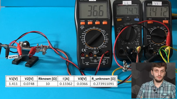
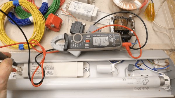
The idea is that wire changes its resistance based on temperature. So if you know the resistance of a lot of wire — maybe a coil — at room temperature and you can measure the resistance at temperature, it is entirely feasible to calculate the amount of temperature that would cause this rise in resistance.

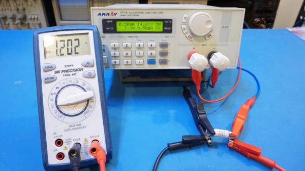
Of course, there are many ways to measure resistance, too. It’s probably possible to measure parameters like operating current and estimate temperature for at least some circuits. The wire’s material also plays a part, and the online calculator lets you choose copper, aluminum, iron, or tungsten. You also need a lot of wire, a very accurate resistance measurement, or, preferably, both.

There are many ways to accurately measure resistance, of course. Then again, you can also get resistors specifically for the job.

Continue reading “Temperature Measurement By Wire”

A schematic for a continuity tester that modulates its pitch based on the resistance measured

Op Amp Contest: Clever Continuity Tester Tells You Where The Problem Is

A continuity tester, as found on most multimeters today, is a great tool for finding broken connections and short circuits. But once you’ve found a short, it’s up to you to figure out which part of the circuit it’s in – a tedious job on a large PCB with hundreds of components. [John Guy] aims to ease this task with a continuity tester that modulates the beeper’s tone according to the resistance measured in the circuit. Tracking down a short circuit is then simply a matter of probing multiple points along a track and observing whether the pitch goes up or down.

The circuit is based on a single AD8534 quad op amp chip. The first stage measures the voltage across the circuit under test in response to small current and amplifies it. The resulting signal is fed into a voltage-controlled oscillator (VCO) made from one op amp connected as an integrator and another working as a comparator with hysteresis. Op amp number four amplifies the resulting square wave and drives a speaker. A low-pass filter makes the sound a bit more pleasing to the ears by removing the higher notes.

[John] paid particular attention to the PCB design to make it easy to assemble despite having a large number of SMD components on a small board. He even placed a parts list on the rear silkscreen, so anyone can assemble it even without the accompanying documents. The resulting board can be placed in a laser-cut acrylic case, turning it into a neat handheld instrument that will definitely find a place in any engineer’s toolbox. Measuring resistance through sound is not as accurate as using a full four-wire setup with an ohmmeter, but will be much faster and easier if you just want to find that annoying solder bridge hiding somewhere on your board.

Programmable Resistance Box

For prototype electronics projects, most of us have a pile of resistors of various values stored somewhere on our tool bench. There are different methods of organizing them for easy access and identification, but for true efficiency a resistance substitution box can be used on the breadboard to quickly change resistance values at a single point in a circuit. Until now it seemed this would be the pinnacle of quickly selecting differently-sized resistors, but thanks to this programmable resistor bank there’s an even better option available now.

Unlike a traditional substitution box or decade box, which uses switches or dials to select different valued resistors across a set of terminals, this one is programmable and uses a series of sealed relays instead. That’s not where the features stop, though. It also comes equipped with internal calibration circuitry which take into account the resistance of the relay contacts and internal wiring to provide a very precise resistance value across its terminals. It’s also able to be calibrated manually to account for temperature or other factors.

For an often-overlooked piece of test equipment, this one surely fits the bill of something we didn’t know we needed until now. Even though digital resistor substitution boxes are things we have featured in the past, the connectivity and calibration capabilities of this one make it intriguing.

How Many Wires Do You Need To Measure A Resistor?

Measuring resistance doesn’t seem to be a big deal. Put your meter leads across two wires or terminals and read the value, right? Most of the time that is good enough, but sometimes you need better methods and for those, you need more wires, as [FesZ] explains in his recent video that you can see below.

In the usual case, the meter applies a known voltage and measures the current which, by Ohm’s law, gives you the resistance. It is also possible to control the current and measure the voltage — doesn’t matter. [FesZ] shows how many meters measure voltage across a known resistor and the unknown so that a precision voltage or current source isn’t necessary.

But there are a number of problems with this simple method. For one thing, the test leads have resistance as well. So some voltage will drop across them, contributing to measurement error. Sure, that extra 0.5 ohms won’t matter if you are looking at a 100K resistor, but if you are trying to measure, say, the heated bed of a 3D printer, that extra 0.5 ohms is a large percentage of the total measurement.

Bench meters for lab use often support 4-wire measurements. As [FesZ] shows, this method measures three different voltages to try to negate some of the measurement errors. We liked that he used three different meters to show how it works and the difference between a 2-wire and 4-wire measurement on a small resistor.

There’s an even stranger method using 3 wires to save on wiring for, say, a sensor a long distance away. There are actually at least two ways to use 3 wires, and the video covers both of them.

For measuring resistors in a circuit, though, you need a whopping six wires. This technique uses the two extra wires to control a balance voltage that keeps the current between the unknown resistor and the rest of the circuit at zero. This prevents current flowing except for the measurement current. You’ll see a simulation of how this works in the video.

We’ve looked at 4-wire measurements before if you want some practice simulations to try. Probes for this measurement are a popular project, too.

Continue reading “How Many Wires Do You Need To Measure A Resistor?”

Kelvin Probes Review Shows How 4-Wire Resistance Measurement Works

You might think the probes in the picture are just funny looking alligator clips. But if you watch [tomtektest’s] recent video, you’ll learn they are really Kelvin probes. Kelvin probes are a special type of probe for making accurate resistance measurements using four wires and, in fact, the probe’s jaws are electrically isolated from each other.

We liked [Tom’s] advice from his old instructor: you aren’t really ever measuring a resistance. You are measuring a voltage and a current. With a four-wire measurement, one pair of wires carries current to the device under test and the other pair of wires measure the voltage drop.

Continue reading “Kelvin Probes Review Shows How 4-Wire Resistance Measurement Works”

Pour Yourself A Glass Of 100,000 Volts

You’d be hard pressed to find a hacker or maker who doesn’t have a soft spot for the tantalizing buzz and snap of a high voltage spark gap, but it remains the sort of project that most of us don’t take on personally. There’s a perceived complexity in building a device capable of shooting a proper spark through several inches of open air, with connotations of exotic components and massive hand-wound coils. Plus, nobody wants to inadvertently singe off their eyebrows.

While the latest video from [Jay Bowles] might not assuage anyone’s fear of performing impromptu electrolysis, it does at least prove that you don’t need to have a laboratory full of gear to produce six figure voltages. In fact, you don’t even need much in the way of electronics: the key components of this DIY Marx generator are made with little more than water and some household items.

This is made possible by the fact that the conductivity of water can be changed depending on what’s been dissolved into it. Straight tap water is a poor enough conductor that tubes of it can be used in place of high voltage resistors, while the addition of some salt and a plastic insulating layer makes for a rudimentary capacitor. You’ll still need wires to connect everything together and some bits of metal to serve as spark gaps, but nothing you won’t find lurking in the parts bin.

Of course, water and a smattering of nails won’t spontaneously generate electricity. You need to give it a bit of a kick start, and for that [Jay] is using a 15,000 volt DC flyback power supply that looks like it may have been built with components salvaged from an old CRT television. While the flyback transformer alone could certainly generate some impressive sparks, this largely liquid Marx generator multiplies the input voltage to produce a serious light show.

We’re always glad to see a new video from the perennially jovial [Jay] come our way. While his projects might not always be practical in the strictest sense, they never fail to inspire a lively discussion about the fascinating applications of high voltage.

Continue reading “Pour Yourself A Glass Of 100,000 Volts”

Test Unknown Fuses Without Destroying Them

There’s a problem with fuses. On the face of it, testing would seem to be a one-shot deal — exceed the rated current and see if it blows. But once you know the answer, the device is useless. If only there were a way to test fuses without damaging them.

As it turns out there is, and [Kerry Wong] weaves quite a tale about his attempts to non-destructively test fuses. The fuses in question are nothing fancy — just the standard glass tube type, from a cheap assortment kit off Amazon. Therein lies the problem: can such cheap devices be trusted? Finding out requires diving much deeper into the technology of fuses than many people will have done, including understanding how the thermal and electrical characteristics of the fuse element behave.

[Kerry]’s test setup is simple, consisting of a constant current power supply and a voltmeter across the fuse to measure the voltage drop caused by the resistance of the fuse element. As he ramps up the current, the voltage drop increases linearly due to the increase in resistance of the alloy with increasing temperature. That only lasts up to a point, where the fuse resistance starts increasing exponentially. Pushing much past the point where the resistance has doubled would blow the fuse, so that’s the endpoint of his tests. Perhaps unsurprisingly, his no-name fuses all went significantly beyond their rated current, proving that you get what you pay for. See the video below for the tests and an analysis of the results.

It’s handy to know there’s a way to check fuses without popping them, and we’ll file this one away for future reference. Don’t forget that you should always check the fuse when troubleshooting, because you never know what the last person did to it.

Continue reading “Test Unknown Fuses Without Destroying Them”