The Kinect Controlled Zombie Skeleton

Although there is no shortage of Kinect hacks out there, this one from Dashhacks seems especially cool.  According to them, the software part of this design uses a “modified OpenNI programming along with GlovePIE to send WiiMote commands to the cyborg such as jaw and torso movement along with MorphVOX to create the voice for the cybernetic monstrosity.” As pointed out in the video, this robotic zombie also has a “pause” feature, and a feature to loop movements like what would be done at an amusement park.

The other great thing about this hack is how well the skeleton is actuated via servo motors. Although it’s difficult to tell how many servos were used for this robot, it certainly has 10 or more degrees of freedom between the head, both arms, and the torso. To control all of this a hacked Wiimote and Nunchuck is used in conjunction with the Kinect. Check out the video after the break.

Continue reading “The Kinect Controlled Zombie Skeleton”

Capturing Video With An Arduino

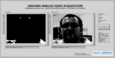
[Carlos Agell] sent in a tip where he captured images from an analog camera with an Arduino.

We’ve seen a few AVR/Arduino hacks that generate video, although overclocking is necessary if you want to do anything beyond a Breakout clone. [Carlos]’ hack bucks that trend and now he can capture video with an Arduino.

The project captures individual frames from NTSC video at a resolution of 128×96. Although the Arduino isn’t powerful enough for real-time capture, [Carlos] managed this by capturing only thresholds and sending them over to a computer running a program coded in LabVIEW. The PC program reassembles the images of the thresholds and produces a tiny image in 3-bit grayscale.

[Carlos] used the Video Experimenter shield which is impressive in it’s own right. The Video Experimenter is able to do object tracking and edge detection, so we’re wondering when we’ll see robots with computer vision running off an Arduino. Check out a demo of the nootropic design video experimenter shield after the break.

UPDATE: Carlos wrote a sketch in Processing that does the same thing as his LabVIEW program.

Continue reading “Capturing Video With An Arduino”

cleaning_pcbs

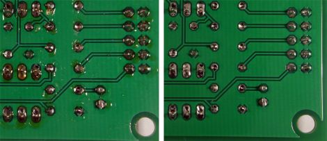
Cleaning Flux From PCBs The Easy Way

While we’re all for building circuits on protoboard or constructing a deadbug circuit for a last minute project, it’s always nice to see a proper PCB now and again. We think that leftover flux can sometimes make even the nicest of circuit boards look a bit dingy, and Hackaday reader [RandomTask] wholeheartedly agrees. He wrote in to share a method he found online that he uses to get his PCBs squeaky clean after soldering.

The secret to his clean PCBs is a product called Poly Clens. It’s essentially a paint brush cleaner that does a great job at removing flux without having to resort to using a brush to scrub it off the board. [RandomTask] simply submerges his newly assembled board in a small container filled with Poly Clens, agitating it for about half a minute or so. After the flux has been removed he rinses it with water, pats it dry, then ensures the board is moisture-free with a few passes of his heat gun.

He says that the entire process takes him less than 5 minutes per board, which is far better than the old alcohol and stiff brush method he used in the past.

What tips or tricks do you have for getting your new projects cleaned up? Be sure to share them with us in the comments.

Hard Drive Teardown

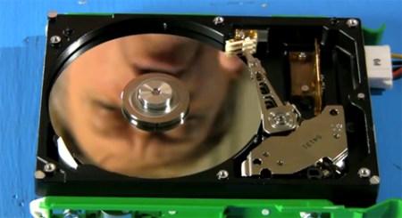
Do you know how a modern hard drive works? If you don’t you should have a pretty good idea after watching this video. In only five minutes [Bill Hammack] manages to describe a hard drive in awesome detail without using any unnecessary scientific jargon.

The video teardown explains how the flying head “flies” how voice coil motors work and provides a basic introduction to how the binary data is stored and processed in the disk. The way the flying head maintains the miniscule distance from the plate is particularly clever. You may remember the LCD monitor teardown by the Engineer Guy, equally as detailed and interesting. The video after the break is definitely worth a watch.

Continue reading “Hard Drive Teardown”

DIY Bolt Together CNC Router

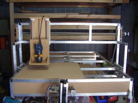
Before I decided to build my own CNC machine I had seen a few bolt together machines on the internet, usually constructed using 80/20 aluminum extrusion. My write up describes my attempt at a completely DIY bolt together machine made from 25mm aluminum SHS, 50mm shelving brackets and lots and lots of gutter bolts.

Building the machine involved drilling and tapping about 400 holes (if I can still count) and assembling the machine over a 3 month period. I designed it mostly on the fly which lead to a few headaches, but in the end a machine that works quite well (if slowly and noisily). I go through each major component of the machine and describe how and why I would have changed it if I had followed the normal plan-design-build methodology.

I have tried two versions of stepper motor drivers and you can find the schematics for the DIY version on my site. The entire thing runs from a Linux PC running EMC2, check out a video after the break to see it in action and here are some photos of a few of my machined items.

Continue reading “DIY Bolt Together CNC Router”

Working With I2C Port Expanders

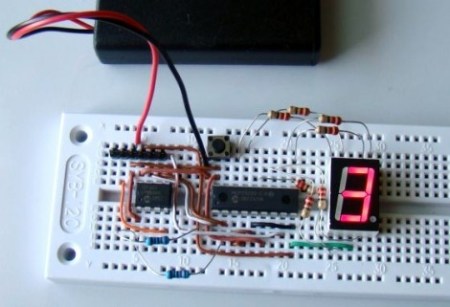
There are times when you don’t need much processing power for your project but you do need a lot of I/O pins. It often doesn’t make economic sense to choose a larger microcontroller just to get extra pins so the answer is to use a port expander chip. [Raendra] posted a guide for using one of these chips, it’s a Microchip MCP23008 chip that uses the I2C protocol for communications.

You are probably already familiar with using shift registers like the 595 series for port expansion. There can be benefits to using an I2C device instead. One of them comes when using multiple port expander chips. With cascading shift registers you must always shift in the data for the entire chain of chips. But I2C devices are individually addressable, so you only need to push data over the I2C bus for the chips that need to be changed, the others will remain unaffected. It is especially easy to use these if you already have another I2C device in your project design as the addition only requires the connection of the SDA and SCL lines. Keep them in mind for future undertakings.

Arduino Hits The Battlefield — For Real

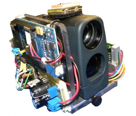
We’re not sure if this is the first time, but here’s some pretty solid proof that Arduino has found its way into the weapons of war. The creators, [Derek Wales], [John Eischer], and [George Hopkins] are all Electronics Engineering majors at West Point. They came up with this idea after seeing video footage of a firefight in Afghanistan where combat soldiers were calling in artillery strikes using a compasses and GPS devices. It’s an all-in-one unit that can provide the same information quickly and accurately. The prototype above, which they call the DemonEye, contains a laser range finder, digital compass, and a GPS module. The article also states that it contains a mini-computer but we recognize that as an Arduino Mega (thanks to Miguel over at Areopago 21 for noticing this first and sending in the tip about it).

The prototype apparently comes in at $1000. Okay, it seems a bit high but not out of the ballpark. What we can’t understand is how the second generation of devices was billed out at $100,000 for five more units. What’s the going rate for laying out military-grade PCBs?