DIY EMG Uses An Audio Recorder

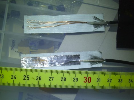
[Ericdsc] is looking to capture the electrical impulses of his muscles by using an EMG. He went through several prototypes to find the right recipe for sensors to pick up the electrical signal through his skin. Above you can see the version that worked best. Each sensor is made starting with a piece of duct tape and laying out a patch of stripped wire on it. A 5cmx1xm piece of aluminum foil then covers this, and second smaller piece of foil covers the cable’s shielding (not pictured here). This will stick to your skin to hold the sensor in place after applying a dab of sugar syrup to help make a good electrical connection.

In this case, an audio recorder is taking the measurements. [Ericdsc] had been having trouble sleeping and wanted to find out if he’s restless in bed. The audio recorder can log hours of data from the sensors which he can later analyze on the computer. Of course, it wouldn’t be hard to build your own amplifier circuit and process the signals in real-time. Maybe you want to convert that mind-controlled Pong game over to use abdominal control. You’ll have a six-pack in no time.

Hackaday Links: June 17, 2012

Portal gag-video

These guys make your own video editing chops look just plain sad. They put together a video demonstrating the portal gun in real life.

Unleashing the beast

We have this problem all the time. The noise regulations were preventing [Massimiliano Rivetti] from letting the true voice of his Ferrari be heard. He hacked into the control system and can now adjust it via iPhone to roar with power. [Thanks Claudio via openPicus]

Music so bad you want to throw something

Here’s a novel way to include the worker bees in music selection around the office. A piezo element was attached to the back of a framed poster and when you throw something at it, the next track is played. We really loved the demo video for this one. [Thanks Calum via DontBelieveTheHype]

Acrylic frame for a CNC machine

[Jake] wrote in to show off his progress on a CNC build. He’s got a frame made of acrylic and some other materials. It’s not up and running yet, but what he’s got so far looks very nice.

Helo built for one

All we can think with this one-man helicopter is failure of those propellers. At least with an ultralight plane you can glide to a gentler crash-landing. [Thanks Filespace]

Ask Hackaday: Has Anyone Built A Radio Telescope?

[Michael] sent in a question regarding the latest advances in software defined radios available for $20 on eBay:

I’ve been looking in to SDR lately, mainly for the possibility of using it for incredibly cheap radio astronomy. So far all I’ve found are whispers. I’m 18 and have very little experience, but I figured you might be able to help me find a little more info.

This really brings me back, [Michael]. I saw Contact in the theater (surprisingly, a rare case when the book and movie are equals), and in my childish exuberance went out and listened to lightning on Jupiter. The financial difficulties of expanding my setup meant the experiments stopped there, but at least I knew amateur radio telescopy was possible.

The latest and greatest advance in software defined radio – namely, a $20 TV tuner dongle – brings something new to the table. Instead of the thousands of dollars in gear that was required in 1997 when I last looked into this, it’s possible to set up a  passable radio telescope for under $100.

I’ll leave it to the Hackaday commentors to fill [Michael] in on the details, but here’s my suggestion:

Optimize your setup for 1420 MHz. There are three reasons for this: firstly, very few things in the universe absorb radio waves at a frequency of 1420MHz; there’s a reason it’s so often used in radio astronomy. Secondly, most government agencies around the world ban (or at least don’t look too kindly upon) transmitting on 1420 MHz. This frequency has been somewhat protected for use by astronomers. Thirdly, most of the Realtek TV tuner dongles have a frequency range of 64 – 1700 MHz, so it’s possible to receive 1420 MHz with this minimal setup.

As far as antennas go, your best bet is probably going to be one of those old C-band parabolic antennas from the 80s. That will make your telescope highly directional and give it a huge amount of gain. There is the problem of having a 20-foot-wide eyesore in your back yard, however. Alternatively, you could use a smaller DirecTV satellite dish, but I’m not making any promises with that. It’ll work, but it’s too small for an optimal setup.

I’ll concede the floor to anyone who has additional information. If you’ve built a radio telescope, send it in and I’ll put it up.

Router Controlling Choo-choos Over The CAN Bus

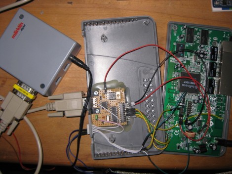
This setup is used to control a model railroad. Well, not entirely this setup. [Gerhard Bertelsmann] already has a proper railroad controller, and it just happens to offer CAN bus communications. He’s using OpenWRT and a cheap router to connect the bus to the network.

Originally he wanted to use a Raspberry Pi board for the project, but the incredible backorder  situation with that hardware led him to grab an old router. After loading OpenWRT he started working out how to connect a couple of ICs (MCP2515 and MCP2551) that will take care of the CAN bus communications. The hardware connections end up being pretty simple, with five data lines (and their pull-up resistors) connecting to the router’s serial header. From there it was a matter of mapping the device in software so that the hardware can be controlled over the network.

We like this example since CAN is used is a lot of other applications.

Using The GPIO Pins On A Raspberry Pi

In addition to being a serviceable single board computer, the Raspberry Pi also has a header full of GPIO pins at your beck and call. [Tedbot] sent in a great tutorial on using these pins with Python, Bash, and C.

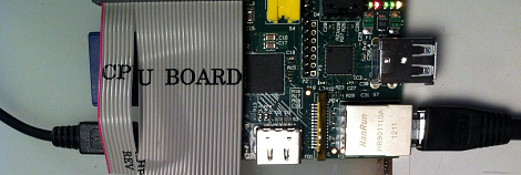
The GPIO pins on the Raspi are arranged in a 2×13 header. Until Sparkfun manages to manufacture a decent Raspi protoboard, the easiest way to break these pins out is with an old IDE ribbon cable. After plugging the other end into a breadboard, [Tedbot] had an easily accessible set of Raspi pins.

To control these pins, [Tedbot] found two libraries: the first is WiringPi that implements a C-style, Arduino-like programming environment on the Raspi. The second is the RPi.GPIO Python package. Since the Raspi runs Linux, and everything in Unix is a file, [Tedbot] used a shell script to blink a LED.

One word of warning if you’re building a board to extend the capabilities of the Raspi: these pins aren’t 5 V tolerant, so you’ll need to throw in a buffer or level converter when building a Raspi circuit.

Edit: Adafruit is releasing a Pi Plate prototyping board in a few weeks. Neat, huh?

BattMan II: The Charger Your Batteries Deserve

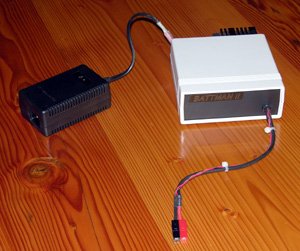
When your radio controlled device batteries are drained, you’ve got no better option than to call on BattMan II. This device is packed full of features for cycling and charging various types of batteries. It is computer controlled via your parallel port (yeah, remember those?) and has companion software that allows you all kinds of control and data.

The writeup is rather extensive and includes schematics so you could build your own. There’s also a step by step breakdown of how each section functions as well as an explanation of each different charging method. Great work [Stefan]

if you just want a peak at the lengthy feature list, keep reading.


Continue reading “BattMan II: The Charger Your Batteries Deserve”

Template For Building STM32F0-Discovery Project In GCC

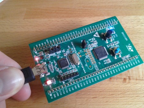
Yep, that blue light is blinking and I made it happen. I’ve been hard at work since I got my free STM32F0-Discovery board in the mail. Most recently I put together a starting template for building STM32F05x project on Linux. You’ll still need to install your own tool chain (I’m using the Code Sourcery G++: Lite Edition), but this makes it a snap to compile your projects with support for STM’s peripheral libraries.

As for programming, you may remember that I added support for writing to RAM in the stlink project. I’ve wasted spent a ton of time trying to get support for writing to Flash into that project. It’s just less of a hassle to use stlink than it is to work with OpenOCD. But I’ve really hit a wall getting the flash loader code to work. If you want to check out what I’ve done so far in that area I committed a very messy branch (see the commits for what code changes I’ve made).

In the mean time you can use OpenOCD to write images compiled with the template to your device. I included the ‘make program’ option in the Makefile to do this from command line. If you need help compiling OpenOCD check the readme in the template repository.