Adding Shoulder Buttons To An RC Transmitter

radio

[Gerard] does puppeteering and animatronics work, and to remotely control his creations and characters he uses an off-the-shelf remote control radio. It’s you basic 6-channel setup, but [Gerard] wanted a way to control eye blinks and other simple actions with the press of a button. Sure, he could use the toggle switches on his transmitter, but he wanted something that wouldn’t require turning a servo on and off again. To fix this problem, [Gerard] added shoulder buttons to his transmitter with only a little bit of soldering.

[Gerard]’s transmitter uses toggle switches to send a signal on channels five and six. To add his push buttons, he simply drilled a hole in the plastic enclosure, installed a pair of push buttons, and wired them in parallel to the toggle switches.

Now [Gerard] has momentary switches on channels five and six, perfect for making his creations blink. Since the buttons are wired in parallel with the switches, flicking the switches to the ‘on’ position in effect takes the button out of the circuit, just in case the transmitter gets jostled around.


Gizmo Board, A Tiny X86 Dev Board

Gizmo

With the Raspberry Pi and sever other ARM dev boards seeing their time in the lime light, it’s no surprise other chip manufacturers would want to get in on the action. AMD is releasing a very tiny x86 dev board called the Gizmo, a four-inch square board that shrinks a desktop computer down to the palm of your hand.

The Gizmo is powered by a dual-core x86 Brazos CPU running at 1 GHz with an included Radeon HD 6250 graphics engine. Also on the board is 1GB of DDR3 RAM, a SATA, Ethernet, USB, VGA, Audio, PCI and PCIe ports, and a ton of GPIO pins that include ADCs and DACs. All this in a four-inch square package that boasts about twice the performance of a Raspberry Pi.

While the price of the Gizmo – $200 for an explorer kit – will probably preclude it from being as popular as a Raspberry Pi or other ARM board, sometimes you just need an x86 platform to do the job. With the powerful graphics potential of the Gizmo, we could easily see this board being used in a few computer vision or autonomous robot builds.

Pinoccio – An Ecosystem For The Internet Of Things

pinoccio-lead-scout-labelled

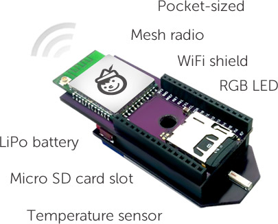
[Pinoccio] is currently an Indeigogo crowd-sourced project that aims use the real-world programmability of the Arduino through the internet using a wifi connection. One could rightly point out that this can already be done through the use of a wifi shield. Before ruling this device out, just “shush your shussins” and consider that it’s designed specifically for interfacing with “things” over the internet. This can replace several components (see 1:10 in the video after the break) and should be less of a hassle.

Additionally, with a shield on one of these devices, several other [Pinoccio] boards can communicate with the Internet using this as a hub in a mesh network. This is similar to how the many “smart” electrical meters work, with a grid router being a central hub for communications. Additionally, this board has a built in temperature sensor and a RGB (instead of a single-color) LED, so you can do some interesting stuff with it right out of the box. Assuming this project gets funded, which seems likely at this point, we’re excited to see the projects that get built using it! Continue reading “Pinoccio – An Ecosystem For The Internet Of Things”

How The 8085 ALU Is Structured

8085-alu-reverse-engineering

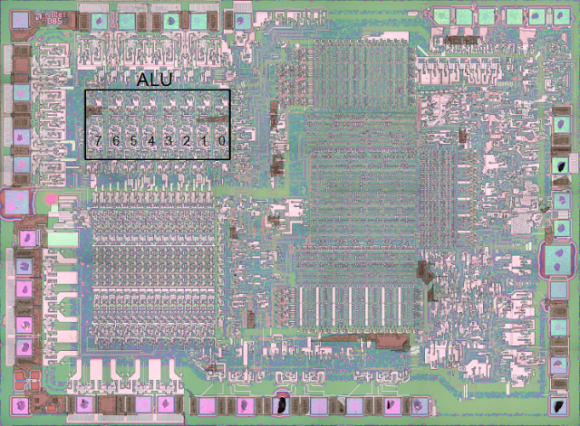
This is a microscopic photograph of an 8085 processor die. [Ken Shirriff] uses the image in his explanation of how the ALU works. It is only capable of five basic operations: ADD, OR, XOR, AND, and SHIFT-RIGHT. [Ken] mentions that the lack of SHIFT-LEFT is made up for by adding the number to itself which has the effect of multiplying a number by two; the same mathematical function performed by a shift operation.

His post details the gate arrangement for each ALU operation. This is clear and easy to follow, and was based on reverse engineering work already done by a team who meticulously decapped and photographed the dies.

Not long ago this explanation would have been voodoo to us. But we worked our way through The Elements of Computing Systems text-book by following the online Nand to Tetris course. It really demystifies the inner working of a chip like the 8085.

Now if you really want to understand this ALU you’ll build it for yourself inside of Minecraft.

[Thanks Ed]

Improved Hourglass Entropy

improved-hour-glass-entropy

[Wardy] built himself a high quality entropy source with parts he had lying around. It’s based on the hourglass entropy project we saw in a links post earlier this month. Just like that project, he is bouncing a laser off of the falling sand and reading the result. But he brings a few innovations to the party, and has test results to back up his work.

The first change is an obvious one; motorize the hourglass so that you don’t need to flip it by hand. We thought this might mess with the laser alignment but the clip after the break proved us wrong. He changed up the sensor, using an LED connected to the base of an NPN transistor. The next change was to mount the light sensor at an angle to the laser rather than straight on. This picks up reflections of the laser and not the direct beam itself, resulting in a wider range of readings.

He used an Ethernet shield to get the system on the network. It’s pushing 420k random numbers per second and was tested with the DieHarder suite. It didn’t get a very high score, but it did pass the test.

Continue reading “Improved Hourglass Entropy”

Announcing: Hackaday Videos And Behind The Scenes Mailing List

hadfilm2

We’re starting a few new things at hackaday. As always, our goal is to share awesome hacks from as diverse a crowd as possible. We’ve played with video a bit before, but now we’re really going to start having some fun with it.

Our first exploration into this area was the hacked portal gun. People enjoyed looking at it, and those seeking more in depth technical knowledge came to the site to get it. Instead of focusing the video on the technology or the build itself, we used it as an interesting way to get the attention of people with relevant interests. This video proved to us that our idea was solid.

We have now stepped up our production in terms of quality and quantity.  We will be releasing videos that may be humorous, like a fake commercial or skit, or may be serious in the style of a documentary. They will all have some kind of hack at their core and that hack will be broken down in an article here.

I would also like to extend the opportunity for you to help. There are two ways you can do so:

  1. Sign up for our email list(it is in the right column). I’ll be sharing behind the scenes info and previews about upcoming video projects and asking for ideas on how to improve them.  The list will be very informal, and only deal with behind the scenes kind of stuff it will not be a mailing of the daily posts.
  2. Submit a project or idea that you think would make a cool video. You can email that directly to caleb@. Of course, we would prefer projects that haven’t been released yet, but that isn’t necessary. We’re looking for things that are visually stunning, or could possibly have highly cinematic potential. Not necessarily the most technically difficult thing.

We hope to start releasing videos next week, so keep your eyes peeled. We filmed all week, and my cheeks hurt from laughing so much.

Raspberry Pi Used As A Beacon Transmitter

rpi-beacon-transmitter

[m0xpd] got his hands on an inexpensive AD9850 DDS Module from eBay but needed a way to control it. He took inspiration from the projects that used a PIC microcontroller, but decided to add his own twist by using a Raspberry Pi to build a multi-mode beacon transmitter.

At the center of this breadboarded circuit lies the green AD9850 module. To its left is a level converter he built to get the 3.3V levels from the RPi board to work with the rest of the 5V hardware. The signal then feeds into a QRP amplifier and a low pass filter.

He didn’t start from square one when it came time to write the code for the RPi. Instead he grabbed an Arduino sketch for the very same DDS and ported it over to Python. The first test signal was his call sign sent in Morse code at QRSS speeds. But he also managed to get Hellschreiber messages working, making it a multiple-mode device.

[via Solder Smoke]