The Development Of A Hardware Random Number Generator

rng

[Ian] had a need for a lot of random numbers. There are dozens of commercial offerings when it comes to RNGs, but there are also hundreds of different ways for an electronics hobbyist to shoot random bits at a serial port. One of these methods is an RNG based on the avalanche breakdown noise in a PN junction. As with any circuit in hobbyist electronics, there are dozens of prototypes floating out there on the web, but not too many finished projects. [Ian] decided he would build one of these RNGs as a prototype and bring it to something resembling a finished project.

An avalanche noise RNG takes advantage of the fact that a strongly reverse-biased PN junction, like one found in a transistor, will create a condition where one electron knocks another electron out of place, leading to a sustained chain reaction. It’s quantum, it’s chaotic, it makes for a great source for a random number generator, and there are already dozens of prototype circuits around the Internet.

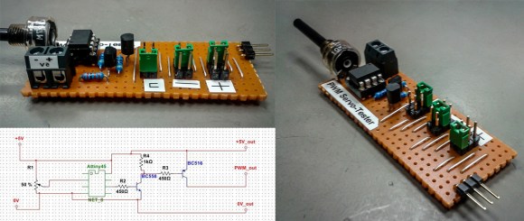
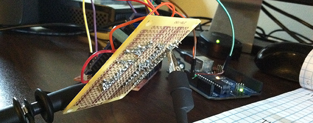
[Ian] took one of these circuit designs by [Will Ware] and started the iterations that would lead to a finished design. Round one was a simple PCB with the basic circuit and a power supply. Just a few transistors, resistors, and a DC/DC boost converter. Confirming the circuit was generating noise, the next iteration brought in an ADC and an ARM micro with a USB interface. Iterating over this again with an improved ADC – 20 megasamples per second – the design finally reached a point where a final PCB could be designed.

In the end, [Ian] turned a simple circuit that could have been built on a breadboard into a USB device that throws 9kB/s of random data into a computer. The data are actually good, too: the project passed most of the Dieharder test suite, making it very useful for whatever crypto or gaming application [Ian] has in mind.

ISEE-3: On Track To Come Home

map
Intended trajectory from ICE team in 1986 (blue), 2001 ephemeris of ISEE-3 (white) and current ephemeris (red/green). Click to embiggen.

When last we heard of the progress of commanding the derelict ISEE-3 satellite into stable orbit between the Earth and the sun, the team had just made contact with the probe using the giant dish in Arecibo, sent a few commands, and started gathering data to plot where the spacecraft is and where it will be. A lot has happened in a week, and the team is now happy to report the spacecraft is alive and well, and much, much closer to the intended trajectory than initially believed.

Before last week, the best data on where ISEE-3 was heading was from a 13-year-old data set, leaving the project coordinators to believe a maneuver of about 50-60  m/s was necessary to put the spacecraft into the correct orbit between the Earth and the sun. With new data from Arecibo, that figure has been reduced to about 5.8 m/s, putting it extremely close to where the original ICE navigation team intended it to go, all the way back in 1986. This also gives the team a bit of breathing room; the original planned maneuver to capture the spacecraft required nearly a third of the available fuel on board. The new plan only requires the spacecraft expend about 5% of its fuel stores. This, of course, brings up the idea of continuing the planned mission of the rebooted ISEE-3 beyond the Earth-Sun L1 point, but that is very much putting the cart before the horse.

Of course, getting ranging data of the spacecraft is only a small part of what has happened with the ISEE-3 part this week. Thanks to the ‘away team’ sent to Arecibo to install hardware and attempt to make contact with the satellite, both transceivers are working, telemetry is being downloaded from the probe, and work has begun on refining the exact position of ISEE-3 to compute where and when the spacecraft needs to make its maneuver.

Regular Hackaday feature and software defined radio god [Balint] was on hand with the away team at Arecibo to install his company’s SDR unit on the largest dish on the planet. His happy dance of the first data from ISEE-3 made the blog rounds, but the presentation (PDF) and photo gallery tell the story of working on the largest dish on the planet much better.

There’s still a lot of work to be done by the ISEE-3 team as they figure out how best to capture the spacecraft and prepare for the burn in the following week. They should have the exact orbit of ISEE-3 nailed down early this week, and after that, ISEE-3 could on a path back home in less than two weeks.

Attiny PWM Generator And Servo Tester

PWM-Servo-Tester

Having the right tool for the job makes all the difference, especially for the types of projects we feature here at Hackaday. [Jana Marie] must agree with this sentiment, one of her latest projects involves building a tool to generate a PWM signal and test servos using an Attiny25/45/85.

Tools come in all kinds of different shapes and sizes. Even if it might not be as widely used as [Jana’s] earlier work that combines an oscilloscope and signal generator, having a tool that you can rely upon to test servos and generate a PWM can be very useful. This well written Instructable provides all the details you need to build your own, including the schematic and the necessary code (available on GitHub). The final PWM generator looks great. For simple projects, sometimes a protoboard is all you need. It would be very cool to see a custom PCB made for this project in the future.

What tools have you build recently? Indeed, there is a tool for every problem. Think outside the (tool) box and let us know what you have made!

Printable Lamp Assembles Itself

Printable-Self-Assembling-Lamp

With the advent of 3D printers, printable circuits, and other “one-machine-to-rule-them-all” automated systems, printing fully functional items is fast becoming a reality. The lamp seen above starts out as a flat piece of cardboard with circuits printed onto it — apply some electricity and it will fold itself up, creating a lamp — it even has a capacitive touch sensor for turning it on!

This ingenuity comes straight from Harvard researchers who presented the project “Self-assembling Sensors for Printable Machines” at the IEEE International Conference on Robotics and Automation (ICRA) just last Tuesday in Hong Kong. It’s not fully printable (wires and the LED had to be soldered in by hand) but it’s an amazing proof of concept — there’s also an Arduino off-screen taking care of controlling it.

The cardboard is a sandwich of shape-memory polymers which are triggered by heat, generated by running electricity through thin layers of copper trace. It takes a long time to assemble so the following video has been sped up 32x speed.

Continue reading “Printable Lamp Assembles Itself”

Customized IPad LCD Screen Clips Onto Macbook As A Slick Second Screen

Macbook with iPad second screen

Last year, [Ben] found a good deal on iPad 3 LCD screens. He couldn’t resist buying a couple to play around with. It didn’t take him long to figure out that it’s actually quite simple to use these LCD screens with any computer. This is because the LCD panels have built-in Apple Display port interfaces. This means that you can add your own Display Port connector to the end of the LCD’s ribbon connector and just plug it into a computer. You’ll also need to hook up a back light driver, which [Ben] was able to find pre-made for around $35.

The hack doesn’t stop there, though. [Ben] wanted to have a nice, finished product. He laser cut an acrylic bezel for the LCD screen that was a perfect fit. He then milled out a space for the LCD to fit into. The acrylic was thick enough to accommodate the screen and all of the cables. To cover up the back, [Ben] chose to use the side panel of a PowerMac G5 computer case. He chose this mainly for aesthetics. He just couldn’t resist the nice brushed aluminum look with the giant Apple logo. It would be a perfect match to his Macbook.

Once the LCD panel was looking nice, [Ben] still needed a way to securely fasten it in the right place. He knew he’d want it next to his Macbook, so why not attach it directly to the Macbook? [Ben] got to work with his 3D printer and printed up some small plastic clips. The clips are glued to the iPad screen’s acrylic bezel and can be easily clipped on and off of the Macbook screen in seconds. This way his laptop is still portable, but he has the extra screen real estate when he needs it. [Ben] also printed up a plastic clip that turns the iPad’s USB power connector and the Display Port connector into one single connector. While this is obviously not required, it does effectively turn two separate plugs into one and makes the whole project that much more slick.

Three-Phase Submersible Thruster Is Open Source And Awesome

submerged_mellon_assembly_v8

Have you ever considered building some kind of underwater vehicle? It’s rather ambitious but [Dane] of Transistor-Man has designed and built a working submersible 3-phase electric thruster — and he’s released the plans online for all to share!

He decided to make this for his 3D printed canoe (another awesome project) which is possible due to his massive SCARA robot 3D printer. The thruster makes use of readily available off the shelf components, but with 3D printed cones for decreased water resistance and other manufactured parts. The housing is water-jet cut, and the poly-carbonate tube had grooves for seals made using a lathe.  The amount of detail in his build logs is incredible — he’s fully modeled all parts in what looks like SolidWorks and uploaded detailed images and designs of all the parts.

The trickiest part of the build was making it water-tight. His first test was to submerge it in a water bath for 8 minutes, and once that was proven, he filled the inside with 5W-20 oil to make sure it wouldn’t leak the other way as well. One of his project goals is for this thruster to work 1 meter underwater without losing more than 10ml of the coolant (oil) per hour.

Continue reading “Three-Phase Submersible Thruster Is Open Source And Awesome”

Track Your Dog With This DIY GPS Harness

GPS-dog-harness

Have you ever wondered how far your dog actually runs when you take it to the park? You could be a standard consumer and purchase a GPS tracking collar for $100 or more, or you could follow [Becky Stern’s] lead and build your own simple but effective GPS tracking harness.

[Becky] used two FLORA modules for this project; The FLORA main board, and the FLORA GPS module. The FLORA main board is essentially a small, sewable Arduino board. The GPS module obviously provides the tracking capabilities, but also has built-in data logging functionality. This means that [Becky] didn’t need to add complexity with any special logging circuit. The GPS coordinates are logged in a raw format, but they can easily be pasted into Google Maps for viewing as demonstrated by [Becky] in the video after the break. The system uses the built-in LED on the FLORA main board to notify the user when the GPS has received a lock and that the program is running.

The whole system runs off of three AAA batteries which, according to [Becky], can provide several hours of tracking. She also installed a small coin cell battery for the GPS module. This provides reserve power for the GPS module so it can remember its previous location. This is not necessary, but it provides a benefit in that the GPS module can remember it’s most recent location and therefore discover its location much faster. Continue reading “Track Your Dog With This DIY GPS Harness”