Hack Your Own Analog Camera

We remember making pinhole cameras as kids out of cigar boxes. The Focal Camera website wants to enable you to make sophisticated cameras from a selection of building blocks. We’re talking cameras with film, not digital cameras (although we wondered if you could mount an image sensor… but that’s another hack).

The modules do require access to a laser cutter, and you’ll need to scrounge or otherwise acquire things like mirrors and lenses. The site has advice on how to hack things like first surface mirrors out of cheap items like acrylic mirrors.

The intent is to be able to build up your own cameras from the modules. They do have a pinhole camera, in case you are nostalgic, but you could also build SLRs, large format cameras, or even stereo cameras. Not all the modules are ready yet, but there are several example cameras and pictures taken with them on the site. Like most building blocks, the real treat will be when users begin to combine them in unexpected ways.

Continue reading “Hack Your Own Analog Camera”

Giant Stepper Motor Gets You Up To Speed On Theory

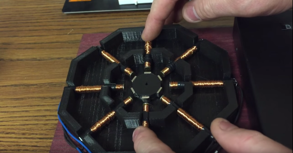
Few hackers have trouble understanding basic electric motors. We’ve all taken apart something that has a permanent magnet DC motor in it and hooked up its two leads to a battery to make it spin. Reverse the polarity, reverse the spin; remove the power, stop the spin. Stepper motors (and their close cousins, brushless DC motors) are a little tougher to grok, though, especially for the beginner. But with a giant 3D printed stepper motor, [Proto G] has made getting your head around electronically commutated motors a little easier.

While we’ve seen 3D printed stepper motors before, the size and simple layout of this one really lends to understanding the theory. With a 3D-printed frame, coils wound on nails, and rare-earth magnets glued to a rotor, this is an approachable build that lays the internals of a stepper motor out for all to see and understand. You can easily watch how the rotor lines up as the various coils are energized in a circular pattern, although it might be more revealing to include bi-color LEDs to indicate which coils are energized and what the polarity is. Those would be especially helpful demonstrating the concept of half-stepping. We’d also like to see more detail on the controller electronics, although admittedly all the video-worthy action is in the motor itself.

Continue reading “Giant Stepper Motor Gets You Up To Speed On Theory”

Learning Verilog For FPGAs: Flip Flops

Last time I talked about how to create an adder in Verilog with an eye to putting it into a Lattice iCEstick board. The adder is a combinatorial circuit and didn’t use a clock. This time, we’ll finish the demo design and add two clocked elements: a latch that remembers if the adder has ever generated a carry and also some counters to divide the 12 MHz clock down to a half-second pulse to blink some of the onboard LEDs.

Why Clocks?

Clocks are an important part of practical digital design. Suppose you have a two input AND gate. Then imagine both inputs go from zero to one, which should take the output from zero to one, also. On paper, that seems reasonable, but in real life, the two signals might not arrive at the same time. So there’s some small period of time where the output is “wrong.” For a single gate, this probably isn’t a big deal since the delay is probably minuscule. But the errors will add up and in a more complex circuit it would be easy to get glitches while the inputs to combinatorial gates change with different delays.

Continue reading “Learning Verilog For FPGAs: Flip Flops”

Tap On! Tap Off! The Backlight!

We recently covered [TechnologyCatalyst’s] excellent $50 multimeter shoot out, and we weren’t surprised when the winner was the Uni-T UT61E. It’s jam packed with features, and has a lot of bang for your buck. But one thing that it’s missing is a backlight.

The 61E uses a chip form CyrusTek called the ES51922A. This chip has a back light features built into it, but Uni-T simply didn’t add the supporting circuitry and LEDs. This was done either to keep cost down, or to not take away sales from their higher end models – your guess is as good as ours. Even though several people have tried carefully soldering to this fine pitch chip package to add back lights, the backlight timer is set to turn off in 60 seconds.

[Nisei] on the EEVBlog forum came up with an elegant capacitive touch solution that we could see being used in many other applications. The mod centers around a using a TTP223 touch sensor module that you can find on eBay for $1 instead of tapping into the meter’s dormant backlight controller. Add in a voltage regulator, a resistor, 2 leds and some foil tape, and that’s about all you need. [Nisei] did a great job documenting the mod with graphics rather than pictures (that can be a bit ambiguous at times.) Also, in case you missed the $50 DMM review you can find it here.

With all that said, we’re thinking the next multimeter mod might just need to be the “Clap-On, Clap-off” meter.

Drivers For 3D Printers And Why We Need Them

Manufacturers of 3D printers have a lot to do before they catch up with makers of the cheapest 2D, paper-based printers. If you’ve ever taken an inkjet apart, you’ll most likely find some sort of closed-loop control on at least one of the axes. The 2D printer will tell you when you’re out of ink, when a 3D printer will go merrily along, printing in air without filament. File formats? Everything is Gcode on a 3D printer, and there are dozens, if not hundreds of page description languages for 2D printers.

The solution to some of these problems are drivers – software for a 3D printer that slowly consumes the slicing of an object, printer settings, and placing an object on the bed. It’s coming, and the people who are responsible for making your 2D printer work with your computer are busy at work messing up the toolchain for your 3D printer.

The latest version of CUPS (C Unix Printing System) adds support for 3D printers. This addition is based on meetings, white papers, and discussions in the Printer Working Group (PWG). There has already been a lot of talk about what is wrong with the current state of 3D printer toolchains, what can be improved, and what should be completely ignored. Let’s take a look at what all of this has accomplished.

Continue reading “Drivers For 3D Printers And Why We Need Them”

Using A Capacitor As An Actuator?!

[Dan Berard] has been using capacitors as actuators.

We’ve featured Dan’s awesome self built STM (scanning tunneling microscope) before. These microscopes work by moving a tip with nanometer precision across a surface. While the images he acquired are great, one disadvantage of the actuator he used is its poor rigidity. This limits the system to faster scan speeds.

In his search for a better actuator [Dan] thought he’d try using MLCC capacitors! While not known for their electromechanical properties, you may have encountered capacitors that appear to “sing” (PDF), emitting an audible tone. This is due to the piezoelectric properties of BaTiO3. Effectively the capacitor acts as a weak piezo electric speaker.

Using a 100V drive voltage [Dan] was able to get 300nm of deflection using the capacitor. To extend the range of the actuator he decided to ‘pole the ceramic dielectric’ this involved heating the capacitor above its Curie temperature of 120C. For this he used a transistor to heat the part as an ad-hoc hotplate. This increased the range of the actuator to 800nm, ideal for many STM (and other SPM) systems.

[Dan] is still weighing up his options for his next build, but MLCC capacitors are certainly a cheap and interesting choice.

High Tech, Low Cost Digital Torque Meter

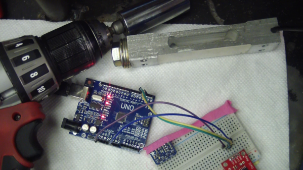
Ever obsessed with stripping the hype from the reality of power tool marketing, and doing so on the cheap, [arduinoversusevil] has come up with a home-brew digital torque meter that does the job of commercial units costing hundreds of times as much.

For those of us used to [AvE]’s YouTube persona, his Instructables post can be a little confusing. No blue smoke is released, nothing is skookum or chowdered, and the weaknesses of specific brands of tools are not hilariously enumerated. For that treatment of this project, you’ll want to see the video after the break. Either way you choose, he shows us how a $6 load cell and a $10 amplifier can be used to accurately measure the torque of your favorite power driver with an Arduino. We’ve seen a few projects based on load cells, like this posture-correcting system, but most of them use the load cell to measure linear forces. [AvE]’s insight that a load cell doesn’t care whether it’s stretched or twisted is the key to making a torque meter that mere mortals can afford.

Looks like low-end load cells might not be up to measuring the output on your high-power pneumatic tools, at least not repeatedly, but they ought to hold up to most electric drivers just fine. And spoiler alert: the Milwaukee driver that [AvE] tested actually lived up to the marketing. Continue reading “High Tech, Low Cost Digital Torque Meter”