I’ve had a few conversations over the years with people about the future of 3D printing. One of the topics that arises frequently is the slicer, the software that turns a 3D model into paths for a 3D printer. I thought it would be a good idea to visualize what slicing, and by extension 3D printing, could be. I’ve always been a proponent of just building something, but sometimes it’s very easy to keep polishing the solution we have now rather than looking for and imagining the solutions that could be. Many of the things I’ll mention have been worked on or solved in one context or another, but not blended into a cohesive package.
I believe that fused deposition modelling (FDM), which is the cheapest and most common technology, can produce parts superior to other production techniques if treated properly. It should be possible to produce parts that handle forces in unique ways such that machining, molding, sintering, and other commonly implemented methods will have a hard time competing with in many applications.
Re-envisioning the slicer is no small task, so I’m going to tackle it in three articles. Part One, here, will cover the improvements yet to be had with the 2D and layer height model of slicing. It is the first and most accessible avenue for improvement in slicing technologies. It will require new software to be written but does not dramatically affect the current construction of 3D printers today. It should translate to every printer currently operating without even a firmware change.
Part Two will involve making mechanical changes to the printer: multiple materials, temperatures, and nozzle sizes at least. The slicer will need to work with the printer’s new capabilities to take full advantage of them.
Finally, in Part Three, we’ll consider adding more axes. A five axis 3D printer with advanced software, differing nozzle geometries, and multi material capabilities will be able to produce parts of significantly reduced weight while incorporating internal features exceeding our current composites in many ways. Five axis paths begin to allow for weaving techniques and advanced “grain” in the layers put down by the 3D printer.
Continue reading “A Look Into The Future Of Slicing” →


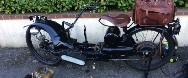
![The Ner-a-Car. By Museumsfotografierer (Own work) [Public domain], via Wikimedia Commons](https://hackaday.com/wp-content/uploads/2016/04/640px-ner-a-car_1924_01.jpg)