Do You Know Oleg Losev? An Engineer Tragically Ahead Of His Time

It is so often the case with a particular technological advance, that it will be invented almost simultaneously by more than one engineer or scientist. People seem to like a convenient tale of a single inventor, so one such person is remembered while the work of all the others who trod the same path is more obscure. Sometimes the name we are familiar with simply managed to reach a patent office first, maybe they were the inventor whose side won their war, or even they could have been a better self-publicist.

When there are close competitors for the crown of inventor then you might just have heard of them, after all they will often feature in the story that grows up around the invention. But what about someone whose work happened decades before the unrelated engineer who replicated it and who the world knows as the inventor? They are simply forgotten, waiting in an archive for someone to perhaps discover them and set the record straight.

Oleg Losev (Public domain)
[Oleg Losev] (Public domain)
Meet [Oleg Losev]. He created the first practical light-emitting diodes and the first semiconductor amplifiers in 1920s Russia, and published his results. Yet the world has never heard of him and knows the work of unrelated American scientists in the period after the Second World War as the inventors of those technologies. His misfortune was to born in the wrong time and place, and to be the victim of some of the early twentieth century’s more turbulent history.

[Oleg Losev] was born in 1903, the son of a retired Russian Imperial Army officer. After the Russian Revolution he was denied the chance of a university education, so worked as a technician first at the Nizhny Novgorod Radio laboratory, and later at the Central Radio Laboratory in Leningrad. There despite his  relatively lowly position he was able to pursue his research interest in semiconductors, and to make his discoveries.

Continue reading “Do You Know Oleg Losev? An Engineer Tragically Ahead Of His Time”

One Soldering Controller To Rule Them All

If your favourite programming language is solder, they you’ve surely worked your way through a bunch of irons and controllers over your hacker existence. It’s also likely you couldn’t pick one single favourite and ended up with a bunch of them crowding your desk. It would be handy to have one controller to rule them all. That’s just what [sparkybg] set out to do by building his Really Universal Soldering Controller. His intent was to design a controller capable of driving any kind of low voltage soldering iron which used either an in-line or separate temperature sensor (either thermocouple or resistive PTC).

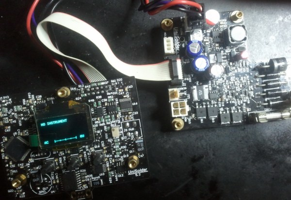
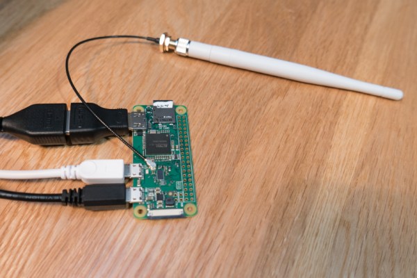
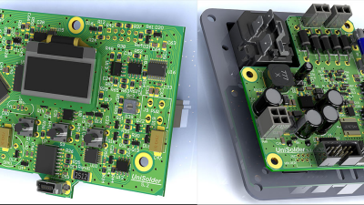
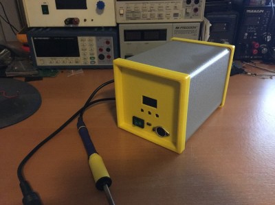
This project has really caught on. [sparkybg] announced his build about two years back and since then many others have started posting details of their own Unisolder 5.2 builds. [zed65] built the version seen to the right and [SZ64] assembled the boards shown at the top of this article.

The controller has been proven to work successfully with Iron handles from Hakko, Pace, JBC, Weller, Ersa, as well as several Chinese makes. Getting the controller to identify one of the supported 625 types of iron profiles consists of connecting two close tolerance resistors across the relevant pins on the 9-pin shell connector. This is a brilliant solution to help identify a large variety of different types of irons with simple hardware. In the unlikely situation where you have a really vague, unsupported model, then creating your own custom profile is quite straightforward. The design is highly discrete with an all analog front end and a PIC32 doing all the digital heavy lifting.

To get an idea of the complexity of his task, here is what [sparkybg] needs to do:

“I have around 200 microseconds to stop the power, wait for the TC voltage to come to its real value, connect the amplifier to this voltage, wait for the amplifier to set its output to what I want to read, take the measurement from the ADC, disconnect the amplifier from the TC, run the PID, and eventually turn the power back on. The millivolts to temperature calculation is done using polynomial with 10 members. It does this calculation using 32bit mantissa floating point numbers and completes it in around 20 microseconds. The whole wave shaping, temperature calculation, PID and so on is completed in around 50-60 microseconds. RMS current, voltage and power calculations are done in around 100 microseconds. All this is done between the half periods of the mains voltage, where the voltage is less than around 3 volts.”

The forum is already over 800 posts deep, but you can start by grabbing the all important schematic PDF’s, Gerbers, BoM and firmware files conveniently linked in the first post to build your own Unisolder5.2 controller. This Universal Controller is a follow up to his earlier project for a Hakko T12/T15 specific controller which gave him a lot of insight in to designing the universal version.

[sparkybg] has posted several videos showing the UniSolder5.2 controlling several types of Irons. In the video after the break, he demonstrates it controlling a Weller WSP80.

Continue reading “One Soldering Controller To Rule Them All”

WikiLeaks Unveils Treasure Trove Of CIA Documents

The latest from WikiLeaks is the largest collection of documents ever released from the CIA. The release, called ‘Vault 7: CIA Hacking Tools Revealed’, is the CIA’s hacking arsenal.

While Vault 7 is only the first part in a series of leaks of documents from the CIA, this leak is itself massive. The documents, available on the WikiLeaks site and available as a torrent, detail the extent of the CIA’s hacking program.

Of note, the CIA has developed numerous 0-day exploits for iOS and Android devices. The ‘Weeping Angel’ exploit for Samsung smart TVs,  “places the target TV in a ‘Fake-Off’ mode, so that the owner falsely believes the TV is off when it is on.” This Fake-Off mode enables a microphone in the TV, records communications in the room, and sends these recordings to a CIA server. Additionally, the CIA has also developed tools to take over vehicle control systems. The purpose of such tools is speculative but could be used to send a moving car off the road.

It is not an exaggeration to say this is the most significant leak from a government agency since Snowden, and possibly since the Pentagon Papers. This is the documentation for the CIA’s cyberwarfare program, and there are more leaks to come. It will be a while until interested parties — Hackaday included — can make sense of this leak, but until then WikiLeaks has published a directory of this release.

Header image source (CC BY 2.0)

Adding An External Antenna To The Raspberry Pi Zero W

Putting a complete WiFi subsystems on a single-board computer is no mean feat, and on as compact a board as the Zero W, it’s quite an achievement. The antenna is the tricky part, since there’s only so much you can do with copper traces.

The new Raspberry Pi Zero W’s antenna is pretty innovative, but sometimes you need an external antenna to reach out and touch someone. Luckily, adding an external antenna to the Zero W isn’t that tough at all, as [Brian Dorey] shows us. The Pi Zero W’s designers thoughtfully included solder pads for an ultra-miniature surface-mount UHF jack. The jack pads are placed very close to the long, curving trace that acts as a feedline to the onboard antenna. There’s even a zero ohm SMT resistor that could be repositioned slightly to feed RF to the UHF jack. A little work with a soldering iron and [Brian]’s Pi was connected to an external antenna.

[Brian] includes test data, but aside from a few outliers, the external antenna doesn’t seem to offer a huge advantage, at least under his test conditions. This speaks to the innovative design of the antenna, which [Roger Thornton] from the Raspberry Pi Foundation discussed during last week’s last week’s Hack Chat. Check out the archive for that and more.

Thanks to [theEngineer] for the tip.

Nvidia Announces Jetson TX2 High Performance Embedded Module

The last year has been great for Nvidia hardware. Nvidia released a graphics card using the Pascal architecture, 1080s are heating up server rooms the world over, and now Nvidia is making yet another move at high-performance, low-power computing. Today, Nvidia announced the Jetson TX2, a credit-card sized module that brings deep learning to the embedded world.

The Jetson TX2 is the follow up to the Jetson TX1. We took a look at it when it was released at the end of 2015, and the feelings were positive with a few caveats. The TX1 is still a very fast, very capable, very low power ARM device that runs Linux. It’s low power, too. The case Nvidia was trying to make for the TX1 wasn’t well communicated, though. This is ultimately a device you attach several cameras to and run OpenCV. This is a machine learning module. Now it appears Nvidia has the sales pitch for their embedded platform down.

Continue reading “Nvidia Announces Jetson TX2 High Performance Embedded Module”

VGA Without A Microcontroller

One of the most challenging projects you could ever do with an 8-bit microcontroller is generating VGA signals. Sending pixels to a screen requires a lot of bandwidth, and despite thousands of hackers working for decades, generating VGA on an 8-bit microcontroller is rarely as good as a low-end video card from twenty years ago.

Instead of futzing around with microcontrollers, [Marcel] had a better idea: why not skip the microcontroller entirely? He’s generating VGA frames from standard logic chips and big ‘ol EEPROMs. It works, and it looks good, too.

VGA signals are just lines and frames, with RGB pixel values stuffed in between horizontal sync pulses, and frames stuffed between vertical sync pulses. If you already know what you want to display, all you have to do is pump the right bits out through a VGA connector fast enough. [Marcel] is doing this by saving images on two parallel EEPROMs, sending the output through a buffer, through a simple resistor DAC, and out through a VGA connector. The timing is handled by a few 74-series four-bit counters, and the clock is a standard 25.175 MHz crystal.

There’s not much to this build, and the entire circuit was assembled on a breadboard. Still, with the clever application of Python to generate the contents of the ROM, [Marcel] was able to build something that displays eight separate images without using a microcontroller.


Open Source Firmware For A Cheap Programmable Power Supply

A few months ago, someone clued us in on a neat little programmable power supply from the usual Chinese retailers. The DPS5005 is a programmable power supply that takes power from a big AC to DC wall wart and turns it into a tiny bench-top power supply. You can pick one of these things up for about thirty bucks, so if you already have a sufficiently large AC to DC converter you can build a nice 250 Watt power supply on the cheap.

[Johan] picked up one of these tiny programmable power supplies. His overall impression was positive, but like so many cheap products on AliExpress, there wasn’t a whole lot of polish to the interface. Additionally, the DPS5005 lacked the ability to be controlled over a serial port or WiFi.

This programmable power supply is built around an STM32, with the programming pads exposed and labeled on the PCB. The changes [Johan] wanted to make were all in software, leading him to develop OpenDPS, a firmware replacement for the DPS5005. Continue reading “Open Source Firmware For A Cheap Programmable Power Supply”