Controlling OctoPrint On The Go

Not too long ago I took the plunge into the world of OctoPrint by shoehorning a Raspberry Pi Zero into a PrintrBot Play, and I have to say, the results were quite impressive. OctoPrint allows you to run your 3D printer untethered from your computer, but without all the downsides of printing off of an SD card. Generally running off of a Raspberry Pi, OctoPrint serves up a very capable web interface that gives you full control over slicing and printing from essentially any device with a modern browser.

That’s all well and good if you’ve got your laptop with you, or you’re sitting at your desktop. But what if you’re out of the house? Or maybe out in the garage where you don’t have a computer setup? OctoPrint is still happily serving up status information and a control interface, you just don’t have a computer to access it. Luckily, there are options for just that scenario.

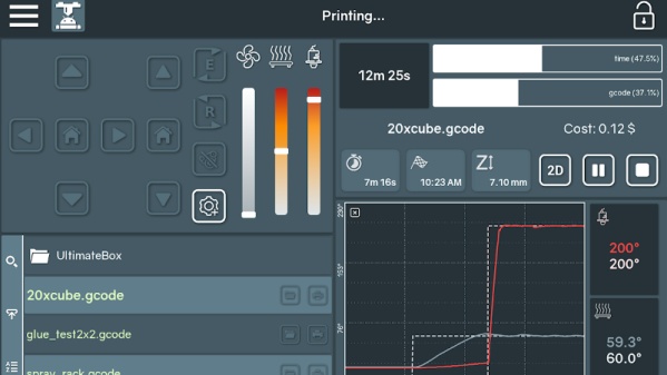
In this post we’re going to take a look at a couple of options for controlling and monitoring OctoPrint from your mobile device, which can help truly realize its potential. Personally I have an incredible amount of anxiety when leaving a 3D printer running a long job, and in the past I’ve found myself checking every 10 minutes or so to see if it was done. Now that I can just glance at my phone and see an ETA along with status information about the machine, it’s given me the confidence to run increasingly longer and complex prints. Continue reading “Controlling OctoPrint On The Go”

3D Printing With Mussels And Beets

What do you get when you combine oven-baked mussels and sugar beets in a kitchen blender? No, it isn’t some new smoothie cleanse or fad diet. It’s an experimental new recyclable 3D printing material developed by [Joost Vette], an Industrial Design Engineering student at Delft University of Technology in the Netherlands. While some of the limitations of the material mean it’s fairly unlikely you’ll be passing over PLA for ground-up shellfish anytime soon, it does have a few compelling features worth looking into.

Joost Vette

For one thing, it’s completely biodegradable. PLA is technically biodegradable as it’s usually made primarily of cornstarch, but in reality, it can be rather difficult to break down. Depending on the conditions, PLA could last years exposed to the elements and not degrade to any significant degree. But [Joost] says his creation degrades readily when exposed to moisture; so much so that he theorizes it could have applications as a water-soluble support material when printing with a multiple extruder machine.

What’s more, after the material has been dissolved into the water, it can be reconstituted and put back into the printer. Failed prints could be recycled directly back into fresh printing material without any special hardware. According to [Joost], this process can be repeated indefinitely with no degradation to the material itself, “A lot of materials become weaker when recycled, this one does not.

So how can you play along at home? The first challenge is finding the proper ratio between water, sugar, and the powder created by grinding up mussel shells necessary to create a smooth paste. It needs to be liquid enough to be extruded by the printer, but firm enough to remain structurally sound until it dries out and takes its final ceramic-like form. As for the 3D printer, it looks like [Joost] is using a paste extruder add-on for the Ultimaker 2, though the printer and extruder combo itself isn’t going to be critical as long as it can push out a material of the same viscosity.

We’ve seen a number of DIY paste extruder mods for 3D printers, which is a good starting point if you’re getting sick of boring old plastic. Before long you might find yourself printing with living tissue.

[Thanks to Mynasru for the tip]

Badgelife: From 1 To 100

Blame it on the falling costs of printed circuit boards, the increased accessibility of hardware design tools, the fact that GCC works on microcontrollers now, whatever the ‘maker movement’ is, or any one of a number of other factors. There’s a hardware demoscene now. Instead of poking bits, writing code, and dividing by zero to create impressive multimedia demonstrations on a computer, there is a small contingent of very creative people who are building their own physical hardware, just for the hell of it. They’re pushing boundaries of what can be done with hardware design, demonstrating manufacturing know-how, and turning a (small) profit while doing it. This is badgelife, the tiny subculture dedicated to creating custom electronic conference badges.

At Hackaday, we’ve been doing a deep dive into the rigors of this demoscene of hardware, and last week we had the pleasure of hosting a meetup with some of the big players of the badgelife community as guests of honor. There were, of course, talks discussing the trials and tribulations of designing, manufacturing, and shipping hundreds of pieces of hardware on a limited budget with not enough time. If you want to know how hard electronic design and manufacturing can be, you want to check out these talks below. Continue reading “Badgelife: From 1 To 100”

Shoot-And-Forget Digital Photo Frame

Digital photo frames these days require you to manage the photos stored on it or the cloud-based service tied to the frame’s manufacturer. [Henric Andersson] realized that he and his wife take a lot of photos but find little time to go through them — like photo albums of days past — and add them to any photo frame-like appliance or service. Since Google photos can do a lot of the sorting for them, he decided to incorporate that into a digital photo frame.

Using his wife’s old Viewsonic 24” 1080p monitor, he cracked it open and incorporated the screen into a 24×16 distressed wood frame — reinforcing it to account for the bulky, built-in power supply with pieces of HDF and a lot of glue. The brains behind this digital photo frame is a Raspberry Pi 3 he received from a friend. To turn the whole on/off, he built a small circuit but it turned out it wasn’t strictly necessary since everything started just fine without it.

While functionally complete, it needed one more addition. A little thing called ‘color temperature calibration’ — aka white balance.

Finding the TCS34725 RGB color sensor by Adafruit — and readily available code for easy integration — [Andersson] puzzled over how to add it to the frame. To disguise it while retaining its effectiveness, he had to glue it to the rear of the frame after drilling a hole in the top piece and sticking a plastic stick through the hole to let light through to the sensor.

To get the photos to display, [Henric Andersson] says all he did was add a few queries to Google Photos and it will display all your relevant photos that have been synced to the service. For a breakdown of that side of this hack, check out his other post with the details.

While Google Photos deftly displays photos of various orientations, sizes, and aspect ratios, we’ve featured a digital photo frame that handles the task a little differently.

FPGA Makes ASCII Video

Human beings like pictures which is probably why there’s the old adage “A picture’s worth a thousand words.” We take computer graphic output for granted now, but even in the earliest days for Teletypes and line printers, there was artwork made from characters ranging from Snoopy to Spock. [Wenting Z] continues the tradition by creating an FPGA that converts VGA video to ASCII art and outputs it via DVI.

The device uses a Xilinx Virtex device and uses about 500 LUT (look up tables) which is not much at all. You can see a video (that includes an overlay of the source video) of the device in action below.

In fact, we think of art like this as a computer phenomenon, but [Flora Stacey] created a butterfly on a typewriter in 1898 and ham radio operators were doing art using paper tape for the last half of the twentieth century. Even before that, In 1865, Alice in Wonderland had a certain passage that was typeset to suggest a mouse’s tail. Perhaps the pinnacle is the famous ASCII version of Star Wars.

This is decidedly less mechanical than some of the other ASCII art projects we’ve seen. If you have a taste for more text art, have a look at some other examples, including a very old advertisement that uses character art.

Continue reading “FPGA Makes ASCII Video”

Graphing Calculator Dual Boots With Pi Zero

The nearly limitless array of consumer gadgets hackers have shoved the Raspberry Pi into should really come as no surprise. The Pi is cheap, well documented, and in the case of the Pi Zero, incredibly compact. It’s like the thing is begging to get grafted into toys, game systems, or anything else that could use a penguin-flavored infusion.

But this particular project takes it to the next level. Rather than just cramming the Pi and a cheap LCD into his Numworks graphing calculator, [Zardam] integrated it into the device so well that you’d swear it was a feature from the factory. By exploiting the fact that the calculator has some convenient solder pads connected to its SPI bus, he was able to create an application which switches the display between the Pi and the calculator at will. With just a press of a button, he’s able to switch between using the stock calculator software and having full access to the internal Pi Zero.

In a very detailed write-up on his site, [Zardam] explains the process of getting the Pi Zero to output video over SPI. The first part of the battle was re-configuring the GPIO pins and DMA controller. After that, there was the small issue of writing a Linux SPI framebuffer driver. Luckily he was able to find some work done previously by [Sprite_TM] which helped him get on the right track. His final driver is able to push 320×240 video at 50 FPS via GPIO, more than enough to kick back with some DOOM.

With video sorted out, he still needed a way to interface the calculator’s keyboard with the Pi. For this, he added a function in his calculator application that echoed the keys pressed to the calculator’s UART port. This is connected to the Pi, where a daemon is listening for key presses. The daemon then generates the appropriate keycodes for the kernel via uinput. [Zardam] acknowledges this part of the system could do with some refinement, but judging by the video after the break, it works well enough for a first version.

We’ve seen the Pi Zero get transplanted into everything from a 56K modem to the venerated Game Boy, and figured nothing would surprise us at this point. But we’ve got to say, this is one of the cleanest and most practical builds we’ve seen yet.

[Thanks to EdS for the tip]

Continue reading “Graphing Calculator Dual Boots With Pi Zero”

Behold The Giant Eye’s Orrery-Like Iris And Pupil Mechanism

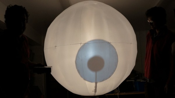
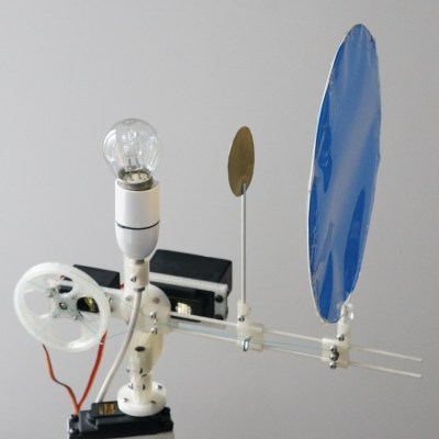
This is an older project, but the electromechanical solution used to create this giant, staring eyeball is worth a peek. [Richard] and [Anton] needed a big, unblinking eyeball that could look in any direction and their solution even provides an adjustable pupil and iris size. Making the pupil dilate or contract on demand is a really nice feature, as well.

The huge fabric sphere is lit from the inside with a light bulb at the center, and the iris and pupil mechanism orbit the bulb like parts of an orrery. By keeping the bulb in the center and orbiting the blue gel (for the iris) and the opaque disk (for the pupil) around the bulb, the eye can appear to gaze in different directions. By adjusting the distance of the disks from the bulb, the size of the iris and pupil can be changed.

A camera system picks out objects (like people) and directs the eye to gaze at them. The system is clever, but the implementation is not perfect. As you can see in the short video embedded below, detection of a person walking by lags badly. Also, there are oscillations present in the motion of the iris and pupil. Still, as a mechanism it’s a beauty.

Continue reading “Behold The Giant Eye’s Orrery-Like Iris And Pupil Mechanism”