Long Live Jibo, Our Adorable Robot Companion

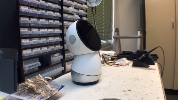
Jibo, the adorable robot made by Jibo, Inc., was getting phased out, but that didn’t stop [Guilherme Martins] from using his robot companion for one last hack.

When he found out that the company would be terminating production of new Jibos and shutting down their servers, he wanted to replace the brain of the robot so that it would continue to live on even after all of its software had become deprecated. By the time the project started, the SDK downloads had already been removed the from developer’s site, so they looked at other options for controlling Jibo.

The first challenge was to not break the form factor in order to disassemble Jibo. They only managed to remove the battery from the bottom, realizing that the glass frame held the brain room. From within the robot, they were able to find the endless rotation joint for the head and the heart of the electronics. Jibo uses a DC motor, encoder, and IR sensor at each of three distinct levels to detect reference points.
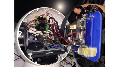
They decided to use Phidgets modules to interface with these devices. While the DC motor controller handles 2A and has an encoder port, the Phidgets are able to provide software with the encoder and PID built-in. The 4x Digital Input Module was used for detecting the IR switch and connecting the modules to the computer.

[Martins] decided to use LattePanda, a hackable Windows 10 development board, for the brain of the new Jibo. The board was luckily able to fit inside the compartment for Jibo, but since it requires more power the unit is powered with 12V regulated to 5V in order to have less current passing through the wires. The DC motors, meanwhile, run at 12V and the IR switches and encoders at 5V.

A program developed in Unity3D plays the eye animations, and a C# program interfaces with the Phidgets. The final configuration was to fit Jibo onto a robotic arm to augment its behaviors. We previously wrote about Toppi, the robotic arm artist, that was used as the base for Jibo’s new home.

You can check out the result in the video below.

Continue reading “Long Live Jibo, Our Adorable Robot Companion”

3D-Printed Transformer Disappoints, But Enlightens

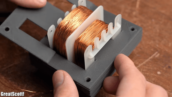
Transformers are deceptively simple devices. Just coils of wire sharing a common core, they tempt you into thinking you can make your own, and in many cases you can. But DIY transformers have their limits, as [Great Scott!] learned when he tried to 3D-print his own power transformer.

To be fair, the bulk of the video below has nothing to do with 3D-printing of transformer coils. The first part concentrates on building transformer cores up from scratch with commercially available punched steel laminations, in much the same way that manufacturers do it. Going through that exercise and the calculations it requires is a great intro to transformer design, and worth the price of admission alone. With the proper number of turns wound onto a bobbin, the laminated E and I pieces were woven together into a core, and the resulting transformer worked pretty much as expected.

The 3D-printed core was another story, though. [Great Scott!] printed E and I pieces from the same iron-infused PLA filament that he used when he 3D-printed a brushless DC motor. The laminations had nowhere near the magnetic flux density of the commercial stampings, though, completely changing the characteristics of the transformer. His conclusion is that a printed transformer isn’t possible, at least not at 50-Hz mains frequency. Printed cores might have a place at RF frequencies, though.

In the end, it wasn’t too surprising a result, but the video is a great intro to transformer design. And we always appreciate the “DIY or Buy” style videos that [Great Scott!] does, like his home-brew DC inverter or build vs. buy lithium-ion battery packs.

Continue reading “3D-Printed Transformer Disappoints, But Enlightens”

Using TL Smoothers For Better 3D Prints

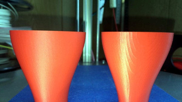
Some 3D printers will give you prints with surfaces resembling salmon skin – not exactly the result you want when you’re looking for a high-quality print job. On bad print jobs, you can usually notice that the surface is shaking – even on the millimeter scale, this is enough to give the print a bumpy finish and ruin the quality of the surface. TL smoothers help with evening out the signal going through stepper motors on a 3D printer, specifically the notoriously noisy DRV8825 motor drivers.

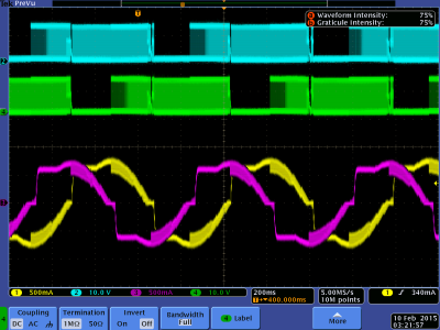
Analyzing the sine wave for the DRV8825 usually shows a stepped signal, rather than a smooth one. Newer chips such as the TMC2100, TMC2208, and TMC2130 do a much better job at providing smooth signals, as do cheaper drivers like the commonly used A4988s.

[Fugatech 3D Printing] demonstrates some prints from a D-Force Mini with an MKS Base 1.4 smoother-based control board, which is easier to use and smarter than Marlin. On the two prints using smoothers, one uses a board with four diodes, while the other was printed with a board with eight diodes. [Mega Making] compares how the different motor drivers work and experimentally shows the stuttering across the different motors before and after connecting to the smoothers.

The yellow and pink traces are the current for each phase of the motor. The blue and green traces are the voltages on each terminal of the phase with the yellow current. [via Schrodinger Z]
A common problem with DRV8825 motors is their voltage rating, which is lower than most supplies. When a 3D printer is moving slower than 100mm/min, the motor is unable to move smoothly.


[Schrodinger Z] does a bit of digging into the reason for the missing microsteps, testing out different decay modes in DRV8825s and why subharmonic oscillations occur in the signals from the motor.

The driver consequently has a “dead zone” where it is unable to produce low currents. Modifying the motor by offsetting the voltage by 1.4V (the point where no current flow) would allow the dead zone to be bridged. This also happens to be the logic behind the design for smoothers, although it is certainly possible to use different diodes to customize the power losses depending on your particular goal for the motor.

Debugging signal problems in a 3D printer can be a huge headache, but it’s also gratifying to understand why microstepping occurs from current analysis.

Continue reading “Using TL Smoothers For Better 3D Prints”

Lane Keeping RC Car Uses OpenCV

Automakers continue to promise that fully autonomous cars are around the corner, but we’re still not quite there yet. However, there are a broad range of driver assist technologies that have come to market in recent years, with lane keeping assist being one of them. [raja_961] decided to implement this technology on an RC car, using a Raspberry Pi.

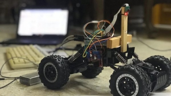
A regular off-the-shelf RC car is used as the base of the platform, outfitted with two drive motors and a third motor used for the steering. Unfortunately, the car can only turn either full-left or full-right only, limiting the finesse of the steering. Despite this, the work continued. A Raspberry Pi 3 was fitted out with a motor controller and camera, and hooked up to the chassis. With everything laced up, a Python script is used along with OpenCV to run the lane-keeping algorithm.

[raja_961] does a great job of explaining the lane keeping methodology. Rather than simply invoking a library and calling it good, instead the Instructable breaks down each stage of how the algorithm works. Incoming images are converted to the HSL color system, before a series of operations is used to pick out the apparent slope of the lane lines. This is then used with a PID algorithm to guide the steering of the car.

It’s a comprehensive explanation of a basic lane-keeping algorithm, and a great place to start if you’re interested in learning about the technology. There’s plenty going on in the world of self-driving RC cars, you just need to know where to look! Video after the break.

Continue reading “Lane Keeping RC Car Uses OpenCV”

Painting With Light: The Homemade Pixelstick

Light painting has long graced the portfolios of long-exposure photographers, but high resolution isn’t usually possible when you’re light painting with human subjects.

This weekend project from [Timmo] uses an ESP8266-based microcontroller and an addressable WS2812-based LED strip to paint words or custom images in thin air. It’s actually based on the Pixelstick, a tool used by professional photographers for setting up animations and photorealism shots. The equipment needed for setting up the light painting sticks runs in the order of hundreds, not to mention the professional camera and lenses needed. Nevertheless, it’s a huge step up from waving around a flashlight with your friends.

The LED Lightpainter takes the Pixelstick a few notches lower for amateur photographers and hobbyists. It directly supports 24-bit BMP, with no conversion needed. Images are stored internally in Flash memory and are uploaded through a web interface. The settings for the number of LEDs, time for the image row, and STA/AP-mode for wireless connections are also set by the web interface. The project uses the Adafruit NeoPixel, ArduinoJson, and Bodmer’s TFT_HX8357 libraries for implementing the BMP drawing code, which also allows for an image preview prior to uploading the code to the microcontroller. Images are drawn from the bottom row to the top, so images have to be transformed before updating to the LED painter.

Some future improvements planned for the project include TFT/OLED support, rainbow or color gradient patterns in the LEDs, and accelerometer or gyroscope support for supporting animation.

There aren’t currently too many galleries of DIY LED-enabled light paintings, but we’d love to see some custom modded light painting approaches in the future.

This isn’t the first LED light stick we’ve seen, if you’re interested in such things.

The Smallest Homebrewed TTL CPU In The World

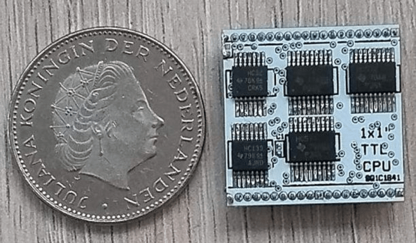
This may very well be the smallest homemade TTL CPU we’ve ever seen. Measuring at one square inch, this tiny chip boasts 40 connections, an 8-bit databus, a 16-bit address bus, a 64 kB memory space, reset and clock inputs, and 5 V power lines.

TTL (transistor transistor logic) logic chips are pretty outdated today, but they do have all of the basics necessary for building a computer – logic gates, counters, buffers, and registers. The transistors perform both the logic and amplifying, as compared to resistor-transistor logic (RTL) and diode-transistor logic (DTL). In the 60s, when the technology was still fairly new, TTL ICs were commonly used in computers and industrial controls. Even after the advent of VLSI, TTL ICs were still being used for interfacing more densely integrated chips. Even so, most TTL chips tend to be on the bulkier side, which is what makes [roelh]’s project so unique. The entire PCB is hardly any larger than a coin.

On top of the hardware specs, [roelh] also implemented several useful software features: zero page addressing, load/store/compare instructions, stacks, conditioning branching, subroutine calls, and memory-mapped I/O. The registers are also in RAM, which has been implemented in microprocessors in the past (see TMS9900) for speed considerations, but in this case was implemented for size constraints.

An ALU was also left out of the design in order to constrain its size, leaving only 8 ICs on either side of the 2-layer PCB.

Microprograms are stored in Flash memory and can be programmed with a Raspberry Pi. by saving the Assembly code to a memory card and downloading the assembled binary code. Once the Raspberry Pi is connected to the development board, you can burn the binary code onto the Flash memory of the board using a Python script. An online Javascript editor also exists for assembling the Assembly code for the chip and simulating the CPU.

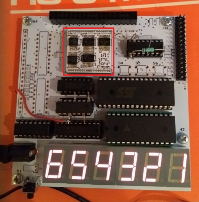
There is currently a development board made for the CPU, which includes six seven-segment displays and an I/O connector for running a digital clock and other applications. [roelh] has since built a retro TTL computer around the chip, which reintroduces the ALU and includes address registers, 256 KB of RAM, VGA video, PS/2 keyboard port, a sound system, and I/O pins. It’s a really exciting project that’s seriously pushing the constraints of retro computing.

RTFM: ADCs And DACs

It’s tough to find a project these days that doesn’t use an analog-to-digital converter (ADC) or digital-to-analog converter (DAC) for something. Whether these converters come as built-in peripherals on a microcontroller, or as separate devices connected over SPI, I2C, or parallel buses, all these converters share some common attributes, and knowing how to read the specs on them can save you a lot of headaches when it comes to getting things working properly.

There are some key things to know about these devices, and the first time you try to navigate a datasheet on one, you may find yourself a bit confused. Let’s take a deep dive into the static (DC) properties of these converters — the AC performance is complex enough to warrant its own follow-up article.

Continue reading “RTFM: ADCs And DACs”