Visualizing Magnetic Memory With Core 64

For the vast majority of us, computer memory is a somewhat abstract idea. Whether you’re declaring a variable in Python or setting a register in Verilog, the data goes — somewhere — and the rest really isn’t your problem. You may have deliberately chosen the exact address to write to, but its not like you can glance at a stick of RAM and see the data. And you almost certainly can’t rewrite it by hand. (If you can do either of those things, let us know.)

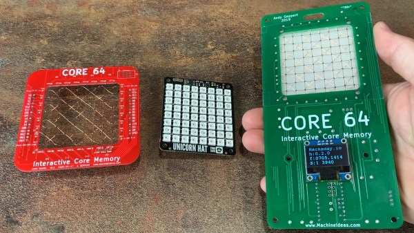
These limitations must have bothered [Andy Geppert], because he set out to bring computer memory into the 
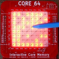
tangible (or at least, visible) world with his interactive memory badge Core 64. [Andy] has gone through a few different iterations, but essentially Core 64 is an 8×8 grid of woven core memory, which stores each bit via magnetic polarization, with a field of LEDs behind it that allow you to visualize what’s stored. The real beauty of this setup is that it it can be used to display 64 pixel graphics. Better yet — a bit can be rewritten by introducing a magnetic field at the wire junction. In other words, throw a magnet on a stick into the mix and you have yourself a tiny drawing tablet!

This isn’t the first time we’ve seen cool experiments with core memory, and not even the first time we’ve seen [Andy] use it to make something awesome, but it really illuminates how the technology works. Being able to not only see memory being written but to manually write to it makes it all so much realer, somehow.

Continue reading “Visualizing Magnetic Memory With Core 64”

Adventures In Overclocking: Which Raspberry Pi 4 Flavor Is Fastest?

There are three different versions of the Raspberry Pi 4 out on the market right now: the “normal” Pi 4 Model B, the Compute Module 4, and the just-released Raspberry Pi 400 computer-in-a-keyboard. They’re all riffing on the same tune, but there are enough differences among them that you might be richer for the choice.

The Pi 4B is easiest to integrate into projects, the CM4 is easiest to break out all the system’s features if you’re designing your own PCB, and the Pi 400 is seemingly aimed at the consumer market, but it has a dark secret: it’s an overclocking monster capable of running full-out at 2.15 GHz indefinitely in its stock configuration.

In retrospect, there were hints dropped everywhere. The system-on-a-chip that runs the show on the Model B is a Broadcom 2711ZPKFSB06B0T, while the SOC on the CM4 and Pi 400 is a 2711ZPKFSB06C0T. If you squint just right, you can make out the revision change from “B” to “C”. And in the CM4 datasheet, there’s a throwaway sentence about it running more efficiently than the Model B. And when I looked inside the Pi 400, there was this giant aluminum heat spreader attached to the SOC, presumably to keep it from overheating within the tight keyboard case. But there was one more clue: the Pi 400 comes clocked by default at 1.8 GHz, instead of 1.5 GHz for the other two, which are sold without a heat-sink.

Can the CM4 keep up with the Pi 400 with a little added aluminum? Will the newer siblings leave the Pi 4 Model B in the dust? Time to play a little overclocking!

Continue reading “Adventures In Overclocking: Which Raspberry Pi 4 Flavor Is Fastest?”

Laser-Induced Graphene Supercapacitors From Kapton Tape

From the sound of reports in the press, graphene is the miracle material that will cure all the world’s ills. It’ll make batteries better, supercharge solar panels, and revolutionize medicine. While a lot of applications for the carbon monolayer are actually out in the market already, there’s still a long way to go before the stuff is in everything, partly because graphene can be very difficult to make.

It doesn’t necessarily have to be so hard, though, as [Zachary Tong] shows us with his laser-induced graphene supercapacitors. His production method couldn’t be simpler, and chances are good you’ve got everything you need to replicate the method in your shop right now. All it takes is a 405-nm laser, a 3D-printer or CNC router, and a roll of Kapton tape. As [Zach] explains, the laser energy converts the polyimide film used as the base material of Kapton into a sort of graphene foam. This foam doesn’t have all the usual properties of monolayer graphene, but it has interesting properties of its own, like extremely high surface area and moderate conductivity.

To make his supercaps, [Zach] stuck some Kapton tape to glass slides and etched a pattern into with the laser. His pattern has closely spaced interdigitated electrodes, which when covered with a weak sulfuric acid electrolyte shows remarkably high capacitance. He played with different patterns and configurations, including stacking tape up into layers, and came up with some pretty big capacitors. As a side project, he used the same method to produce a remarkable effective Kapton-tape heating element, which could have tons of applications.

Here’s hoping that [Zach]’s quick and easy graphene method inspires further experimentation. To get you started, check out our deep-dive into Kapton and how not every miracle material lives up to its promise.

Continue reading “Laser-Induced Graphene Supercapacitors From Kapton Tape”

Tensions High After Second Failed Cable At Arecibo

Today we’re sad to report that one of the primary support cables at the Arecibo Observatory has snapped, nudging the troubled radio telescope closer to a potential disaster. The Observatory’s 300 meter reflector dish was already badly in need of repairs after spending 60 years exposed to the elements in Puerto Rico, but dwindling funds have made it difficult for engineers to keep up. Damage from 2017’s Hurricane Maria was still being repaired when a secondary support cable broke free and smashed through the dish back in August, leading to grave concerns over how much more abuse the structure can take before a catastrophic failure is inevitable.

The situation is particularly dire because both of the failed cables were attached to the same tower. Each of the remaining cables is now supporting more weight than ever before, increasing the likelihood of another failure. Unless engineers can support the dish and ease the stress on these cables, the entire structure could be brought down by a domino effect; with each cable snapping in succession as the demands on them become too great.

Workers installing the reflector’s mesh panels in 1963.

As a precaution the site has been closed to all non-essential personnel, and to limit the risk to workers, drones are being used to evaluate the dish and cabling as engineers formulate plans to stabilize the structure until replacement cables arrive. Fortunately, they have something of a head start.

Back in September the University of Central Florida, which manages the Arecibo Observatory, contacted several firms to strategize ways they could address the previously failed cable and the damage it caused. Those plans have now been pushed up in response to this latest setback.

Unfortunately, there’s still a question of funding. There were fears that the Observatory would have to be shuttered after Hurricane Maria hit simply because there wasn’t enough money in the budget to perform the relatively minor repairs necessary. The University of Central Florida stepped in and provided the funding necessary to keep the Observatory online in 2018, but they may need to lean on their partner the National Science Foundation to help cover the repair bill they’ve run up since then.

The Arecibo Observatory is a unique installation, and its destruction would be an incredible blow for the scientific community. Researchers were already struggling with the prospect of repairs putting the powerful radio telescope out of commission for a year or more, but now it seems there’s a very real possibility the Observatory may be lost. Here’s hoping that teams on the ground can safely stabilize the iconic instrument so it can continue exploring deep space for years to come.

Trying (And Failing) To Use GPUs With The Compute Module 4

The Raspberry Pi platform grows more capable and powerful with each iteration. With that said, they’re still not the go-to for high powered computing, and their external interfaces are limited for reasons of cost and scope. Despite this, people like [Jeff Geerling] strive to push the platform to its limits on a regular basis. Unfortunately, [Jeff’s] recent experiments with GPUs hit a hard stop that he’s as yet unable to overcome.

With the release of the new Compute Module 4, the Raspberry Pi ecosystem now has a device that has a PCI-Express 2.0 1x interface as stock. This lead to many questioning whether or not GPUs could be used with the hardware. [Jeff] was determined to find out, buying a pair of older ATI and NVIDIA GPUs to play with.

Immediate results were underwhelming, with no output whatsoever after plugging the modules in. Of course, [Jeff] didn’t expect things to be plug and play, so dug into the kernel messages to find out where the problems lay. The first problem was the Pi’s limited Base Address Space; GPUs need a significant chunk of memory allocated in the BAR to work. With the CM4’s BAR expanded from 64MB to 1GB, the cards appeared to be properly recognised and ARM drivers were able to be installed.

Alas, the story ends for now without success. Both NVIDIA and ATI drivers failed to properly initialise the cards. The latter driver throws an error due to the Raspberry Pi failing to account for the I/O BAR space, a legacy x86 feature, however others suggest the problem may lay elsewhere. While [Jeff] may not have pulled off the feat yet, he got close, and we suspect with a little more work the community will find a solution. Given ARM drivers exist for these GPUs, we’re sure it’s just a matter of time.

For more of a breakdown on the Compute Module 4, check out our comprehensive article. Video after the break.

Continue reading “Trying (And Failing) To Use GPUs With The Compute Module 4”

Retrotechtacular: Shake Hands With Danger

OK, you’re going to have to engage your safety squints and sit back to enjoy this one: a classic bit of safety propaganda from US heavy-equipment manufacturer Caterpillar from 1980 entitled “Shake Hands with Danger.”

Actually, you’ll probably need to engage your schlock filters for this 23-minute film too, as both the writing and the theme song are pretty hard to take. The film is one of those “Scared Straight” attempts to show just how horrifically wrong things can go both in the field and in the shop when working on anything made of stuff stronger than human flesh and bone. And in that regard, the film is highly effective — we found ourselves getting a bit queasy at a few points, with the poor dude who got his hand sucked into a bench grinder being both terrifying and relatable. [Three-Finger Joe] indeed.

Now, you might take exception with the acting, but as you watch all these vignettes, keep in mind that these are all old-school stunts — that’s actually a gigantic D9 bulldozer they crashed, and that brake chamber explosion really blew out that truck’s windows. They did a great job making the potential consequences of a moment’s thoughtlessness sickeningly vivid. Especially that arm-in-the-linkages scene. Ugh.

Whatever way you practice the hacking arts, stay safe out there. And don’t “Shake Hands with Danger.”

Continue reading “Retrotechtacular: Shake Hands With Danger”

Xbox Series S Teardown Photo

Xbox Series S Teardown Shows A Glimpse At The Future

Console launch season is upon us. A time for billion dollar corporations ingratiate themselves with “Johnny Consumer” by promising the future of entertainment is finally available to one-and-all. The focus of this new generation of consoles has been the battle for 4K supremacy between Xbox Series X and PlayStation 5. Interestingly, Microsoft also created another iteration of their Xbox Series for those satisfied with games in 1080p, and thanks to [Dimitris] we have been able to see the internals of the Xbox Series S (XSS).

Xbox Series S Teardown SSD Photo
The Xbox Series S features standard m.2 slot that could be used for future storage expansion.

Microsoft’s choice to produce an all-digital console has greatly affected the internal design of the XSS. With the lack of a disc-drive there is only a single cable, the fan cable, tying the components together. The heat sink covering the 197mm² AMD APU takes up nearly 60% of the motherboard surface area. Though the XSS may be diminutive by modern console standards, its cooling fan is huge, somewhere in the 140 mm range. What little space is left by the heat sink and fan assembly is taken up by the internal power supply. As a fun nod, the PSU sports a Master Chief insignia to denote the location of the two-pronged connector beneath.

On the underside of the motherboard lies the biggest surprise of the “little brother” console. The system storage SSD is socketed rather than directly soldered to the board itself. The primary design goal of the XSS was to provide a cheaper alternative for players, but this standard m.2 slot reveals that Microsoft has plans for future expansion. This SSD, while not user-accessible in a traditional sense, will likely provide an alternative method to expanding storage outside of Microsoft’s proprietary external offerings. For a look at the teardown in process, [Dimitris’] video from his Modern Vintage Gamer YouTube channel is below.

Continue reading “Xbox Series S Teardown Shows A Glimpse At The Future”