Animatronic Cosplay Wings

In recent years, Cosplay as a hobby has seen improvement in the props department by leaps and bounds. Thanks in part due to the rise of the Maker culture and the easy availability of design and manufacturing tools and processes. Case in point is this awesome set of Animatronic Wings that programmer [Nelson Stoldt] built for his daughter who wanted to be Nightmare Moon.

[Nelson] had no idea what he’d gotten himself in to when he answered “Sure, I can do that”. Making motorized cosplay wings that open up to 8 feet wide and close again at the flick of a switch without weighing a ton is not a trivial project. The final rig did end up tipping the scales at just over 9 kgs, but we guess that’s a load that Cosplayers are used to hauling around.

Using a nifty program called Linkage, he played around with a few different design approaches until he found a mechanism that worked well. If you ever want to build one of [Theo Jansen]’s Strandbeest, give this program a spin. Armed with this information, and a spreadsheet to help determine the exact length of each linkage element, he modelled the project in Sketchup. The wings are operated by a scissor mechanism that is driven by a motorized screw operated sliding carriage. Wing position is measured by a potentiometer coupled to one of the wing elements. Basically, he just built a huge, powerful servo.

Continue reading “Animatronic Cosplay Wings”

7 LED’s, 2 Pins – Beat That, Charlieplexing

[Tim]’s Dice10 is an exercise in minimalism. Building an electronic dice using an ATtiny10 with code that fits within 1kB is not too difficult. Charlieplexing the LED’s would have used three of the four available GPIO pins. [Tim] upped the game by using just two GPIO pins to drive the seven LED’s for the dice. A third GPIO is used as a touch button input. Besides the ATtiny and the LED’s, the only other component used is a capacitor across the supply inputs.

2 GPIO for 7 LED's
2 GPIO for 7 LED’s

The LED’s are grouped in three pairs of two LED’s and a single centre LED. Usually, Charlieplexed LED’s are connected across pairs of GPIO pins. But his scheme includes connections to the 5V and GND terminals, besides the two GPIO pins. Building a truth table makes it easy to figure out what’s going on.

STATE PB2 PB0 LED's
1     Z   Z   --
2     L   Z   LED 1/2
3     H   Z   LED 3/4
4     Z   L   LED 5/6
5     Z   H   --
6     H   L   LED9
7     L   H   --
8     H   H   --
9     L   L   --

Only the logic states used are listed in the table. It’s possible to add two more LED’s between PB0 and GND and one more anti-parallel with LED9, making a total of 10 LED’s driven by two pins. That’s quite a hack. The important thing here is to have two LED’s in series in the arms that connect to either 5V or GND.

[Tim] has posted  the code and hardware source files on his Github repo, and his blog post has some additional details on how he solved the problem.

If you’re looking for more inspirations on minimal dice designs, check this “PIC powered pair of electronic dice” which uses a PIC 12F629 with five outputs driving a pair of 7 pips to make a dual dice.

1kb-thumb

If you have a cool project in mind, there is still plenty of time to enter the 1 kB Challenge! Deadline is January 5, so check it out and fire up your assemblers!

Christmas Lights Done The Hard Way

It’s that time of the year again when you gotta start worrying if you’ve been naughty enough to not receive any gifts. Hopefully, Blinky Lights will appease St. Nick. Grab a strip of RGB LEDs, hook them up to an Arduino and a Power supply, slap on some code, and Bob’s your Uncle. But if you want to retain your hacker cred, you best do it the hard way. Which is what [roddersblog] did while building his Christmas Starburst LED Stars this year — and bonus points for being early to the party.

christmas-lights-the-hard-wayFor starters, he got panels (as in PCB panels) of WS2812 boards from eBay. The advantage is it lets you choose your own pitch and strand length. The flip side is, you need to de-panel each board, mount it in a jig, and then solder three lengths of hook up wire to each LED. He planned for an eight sided star with ten LED’s each. And he built three of them. So the wiring was, substantial, to say the least. And he had to deal with silicone sealant that refused to cure and harden. But nothing that some grit and determination couldn’t fix.

For control, he choose the PIC16F1509 microcontroller. This family has a feature that PIC calls the “Configurable Logic Cell” and this Application Note describes how to use CLC to interface the PIC to a WS2811. He noticed processing delays due to C code overheads that caused him some grief. After some experimentation, he re-wrote the entire program in assembly which produced satisfactory results. You can check out his code on the GitHub repository.

Also well worth a look, he’s got a few tricks up his sleeve to improve the quality of his home-brew PCB’s. He’s built his own UV exposure unit with timer, which is an interesting project in itself. The layout is designed in Eagle, with a flood fill to minimize the amount of copper required to be etched away. He takes a laser print of the layout, applies vegetable oil to the paper to make it more translucent to UV, and doubles up the prints to get a nice contrast.

Once the sensitized board has been exposed in the UV unit, he uses a weak but fresh and warm solution of Sodium Hydroxide as a developer to remove the unexposed UV photo-resist. To etch the board, he uses standard Feric Chloride solution, which is kept warm using an aquarium heater, while an aquarium air-pump is used to agitate the solution. He also describes how he fabricates double sided boards using the same technique. The end result is quite satisfying – check out the video after the break.

Continue reading “Christmas Lights Done The Hard Way”

Turn Cheap USB Soldering Irons In To Tweezers

This is 2016, and almost every hacker dabbles with SMD parts now, unlike back in the day. This means investing in at least some specialized tools and equipment to make the job easier. One handy tool is the SMD soldering tweezers – useful not only for manual soldering of parts, but also for de-soldering them quickly and without causing damage to the part or the board. Often, especially when repairing stuff, using a hot air gun can get tricky if you want to remove just one tiny part.

smd_tweezer_04
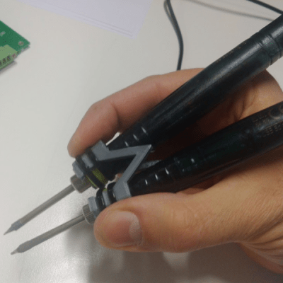
[adria.junyent-ferre] took a pair of cheap £5 USB soldering irons and turned them into a nifty pair of SMD soldering tweezers. The two irons are coupled together using a simple, 3D printed part. [adria]’s been through a couple of iterations, so the final version ought to work quite well. The video after the break shows him quickly de-soldering a bunch of 0805 SMD resistors in quick succession.

Earlier this year, we had posted [BigClive]’s tear down of these 8 watt USB soldering irons which turned out to be surprisingly capable and this spurred [adria] to order a couple to try them out.

The 3D printed part is modeled in SolveSpace – a parametric 2D and 3D CAD software that we blogged about a while ago. Continue reading “Turn Cheap USB Soldering Irons In To Tweezers”

JOLED – A 3D Flip Dot Display

Flip-Dot displays are so awesome that they’re making a comeback. But awesome is nothing when you can have an insane flip-dot display that is three-dimensional with the dots floating in mid-air. Researchers at the Universities of Sussex and Bristol have built what they call JOLED, an array of floating pixels that can be controlled via a combination of ultrasonic standing waves and an electrostatic field. These “voxels” can be individually moved in space via ultrasonics, and can also be individually flipped or rotated through any angle, via the electrostatic field.

The key to the whole thing is something they call Janus Objects – hence JOLED. Janus particles have different features or chemistry on two opposite sides. A portion of each voxel is speckled with a small amount of titanium dioxide nano powder. This gives it a bipolar charge that makes it respond to the variable electrostatic field and hence capable of axial rotation. Half of each white voxel can then be covered with a contrasting color – red, blue, black – to achieve the flip dot effect. Each voxel appears to be a couple of millimeters in diameter. The ultrasonic actuators appear to be regular piezo transmitters found in every hacker’s parts bin. Transparent glass plates on opposite sides apply the variable electrostatic field.

While this is still experimental and confined to the research lab, future applications would be interesting. It would be like breaking e-ink displays out of their flat glass confines and giving them a third dimension. The short, two-minute video after the break does a good job of explaining what’s going on, so check it out. Now, who want’s to be the first to build a JOLED clock?

Thanks to [Garrow] for tipping us off about this.

Continue reading “JOLED – A 3D Flip Dot Display”

7 Segment Display Using Neopixel Rings

There’s something about clocks — sooner or later, every hacker wants to build one. And we end up seeing all kinds of display techniques being used to show time. For the simplest of builds, 7-segment display modules usually get dug up from the parts bin. If you have a bunch of “smart” LED’s (WS2812’s, APA102’s), then building your own custom 7-segment modules isn’t too difficult either. [rhoalt] had neither, but he did have several 8 LED Neopixel rings lying around. So he thought of experimenting with those, and built a ‘Binoctular’ LED clock which uses the Neopixel rings as 7 segment displays.

figure-eight-segment-displays
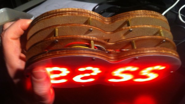
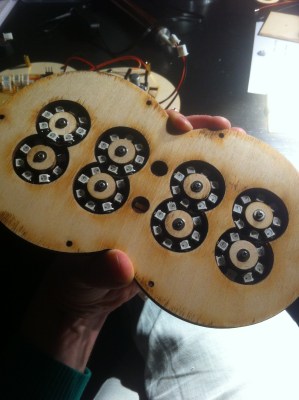
Each digit is made using one pair of Neopixel rings, stacked to form a figure of eight. All the digits are composed of arcs, so readability isn’t the best but it’s not hard either. [rhoalt] does mention that the display is easier to read via blurred camera images rather than visually, which isn’t surprising. We’re long used to seeing numbers composed of straight line segments, so arc segmented digits do look weird. But we wouldn’t have known this if [rhoalt] hadn’t shown us, right ? Maybe a thicker diffuser with separator baffles may improve the readability.

The rest of the build is pretty plain vanilla — an Arduino Nano clone, a DS3231 RTC, a Lithium battery, and some buttons, all housed together in a laser cut enclosure which follows the figure of eight design brief. And as usual, once you’ve built one, it’s time to improve and make a better version.

NixieBot Films Your Tweets

[Robin Bussell]’s NixieBot is a mash up of new age electronics and retro vintage components and he’s got a bunch of hacks crammed in there. It’s a Nixie tube clock which displays tweets, takes pictures of the display when it encounters tweets with a #NixieBotShowMe hash tag, and then posts requested pictures back to twitter. If a word is eight characters, it takes a snapshot. If it’s a longer message, NixieBot takes a series of pictures of each word, converts it to an animated GIF, and then posts the tweet. In between, it displays random tweets every twenty seconds. You can see the camera setup in the image below and you should check out the @nixiebot twitter feed to see some of the action.

nixiebot_05
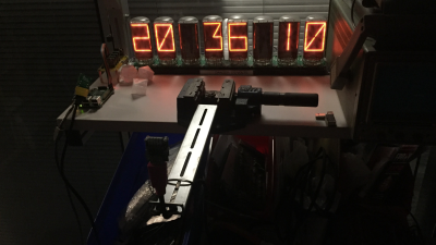
For the display, he’s using eight big vintage Burroughs B7971 Nixie Tubes. These aren’t easy to source, and current prices hover around $100 each if you can find them. The 170V DC needed to run each tube comes from a set of six 12V to 170V converter boards specifically designed to drive these tubes. Each board can drive at least a couple of nixies, so [Robin]’s able to use just four boards for the eight tubes. Each nixie is driven by its own “B7971 SmartSocket“, a dedicated PIC16F690 micro-controller board custom designed for the purpose. A serial protocol makes it easy to daisy-chain the SmartSockets to build multi character displays.

Continue reading “NixieBot Films Your Tweets”