IoT protocols are a relatively unexplored field compared to most PC-exposed protocols – it’s bothersome to need a whole radio setup before you can tinker on something, and often, for low-level experiments, just any radio won’t do. This means there’s quite a bit of security ground to cover. Now, the U-Fuzz toolkit from [asset-group] helps us make up for it.
Unlike fuzzers you might imagine, U-Fuzz doesn’t go in blindly. This toolkit has provisions to parse protocols and fuzz fields meaningfully, which helps because many of devices will discard packets they deem too malformed. With U-Fuzz, you feed it a couple packet captures, help it make some conclusions about packet and protocol structure, and get suggestions on how to crash your devices in ways not yet foreseen.
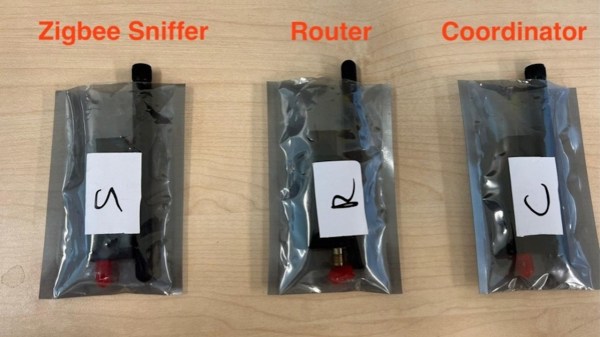
This allows for basically arbitrary protocol fuzzing, and to demonstrate, we get examples on 5G, CoAP and ZigBee probing alike, with a list of found CVEs to wrap the README up. As Wikipedia often states, this list is incomplete, and you can help by expanding it. Fuzzing is an underestimated tool – it will help you hack ubiquitous wireless protocols, proprietary standards, and smart home hubs alike.