We started with figuring out HID descriptors a week ago, and I’ve shown you how to send raw HID packets using a MicroPython fork. We do still have the task in front of us – making a touchscreen device. For that, let’s give you the tools to capture an existing descriptor from a touchscreen, then show you how to tweak it and how it turns out in the end.
Packing For The Heist
When it comes to this kind of adventure, we can’t go without tools and weapons – it could be dangerous! Without them, you could even abandon your project halfway! Here’s enough high-precision tools and ammunition to last you through whatever obstacles you might encounter. Except for the web-based tools, these tools are for Linux, but please remember that you can always use a virtual machine or a Raspberry Pi. Nobody would use Windows for a heist anyway, what’s with all the telemetry and such.
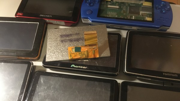
The first tool is for reading descriptors – we need one to learn from, it’s just like a keycard you can flash to a security guard and scan at the vault entry. Of course, with RFID, you want to have enough examples, compare bits between a few cards and all. For now, HID descriptors don’t have authenticity checks, but it looks like that might just change in the future. Leave it to Apple and Microsoft to add them, as usual. On Linux, seeing descriptors is simple – as root, go into /sys/bus/usb/devices/, find your device by its lsusb device tree path, then follow the directory with the VID/PID in it. That directory will contain a report_descriptor file – hexdump it. The entire command could look like this:
sudo hexdump -v -e '/1 "%02X "' /sys/bus/usb/devices/3-6.2/3-6.2\:1.1/0003\:0C40\:8000.0022/report_descriptor
Again, you might need root to even find this path, so use sudo -i if you must. The format string in the hexdump command gives you parser-friendly output. Specifically, for parsing, I use this webpage – it’s wonderful, even adding tabs that delineate different sections of the descriptor, making its output all that more readable! You can also save this webpage locally, it’s a very neat tool. Other than that, you can try other local tools like this one!
Continue reading “Human-Interfacing Devices: Packing For The Descriptor Heist”


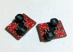 However, for some, switching regulators might look a bit intimidating. They tend to have higher standards for board layout compared to linear regulators, and, they do need an inductor – sometimes, a few more components too. Inductors alone are somewhat intimidating components, with a fair few more parameters than we’d expect, and you might get confused when looking into adding a switching regulator to your circuit.