Using LVDS Laptop Displays

No doubt anyone reading this has access to a few ancient laptops and the displays contained within. While those laptops are probably still stuck with a Gig of RAM and Windows ME, the display panels are probably still good. They don’t have HDMI, DVI, or VGA, though, which means those panels will need a converter.

[Jared] had a different idea. Instead of reusing laptop displays with a converter, why not connect them to an LVDS connector on some modern hardware? He had a RIoT board with a native LVDS connector, and with some clever reverse engineering and PCB fabrication he can put those old displays to work.

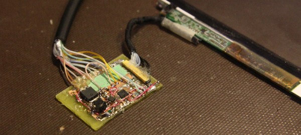
[Jared] had a very cool sunlight-readable ‘transflective’ LCD from on old Portege R500 laptop. If he was going to take apart one laptop to use with modern hardware, this was the one. Opening up the display he found a tiny connector but no obvious markings of what pins did what. The datasheet was also not to be found. By shorting two pins together, he could figure out what the pins were: shorting the clock freezes the screen, shorting the HSYNC and VSYNC means the screen loses sync. Blues, reds, and greens can be found the same way.

With the pins identified, a breakout board was in order. This is just a small board to break out the very small wires to solderable pads and a driver for the backlight. With that, and the RIoT with an LVDS output, [Jared] was able to use new hardware with this old but still serviceable display.
High Voltage AVR Programmer

The most common way of programming AVR microcontrollers is the In System Programming port. That little six-pin header with MOSIs and MISOs coming out of it will program every AVR you’ll ever come across. The ISP does have a downside – fuses. Set your fuses wrong, and without a High Voltage Serial Programmer, your chip is bricked. [Dilshan] designed his own HVSP that’s less expensive than the Atmel STK500 and has a nice GUI app.

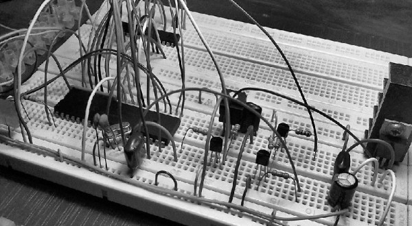
Instead of following in the footsteps of the USBtinyISP, [Dilshan] is using a PIC18F as the main microcontroller in the programmer. This chip was chosen because of its built-in USB functionality. Because the High Voltage part of a HVSP operates at 12V, actually providing that voltage needed to be taken into consideration. For this, [Dilshan] is using standard 78xx regulators with an 18V input.

The app to control this programmer does everything you would expect, including all the usual AVRdude commands. A great build, and just what we need to reset the fuses on a few dozen chips we have sitting around.

How To Properly Crimp Electronics Connectors

Putting crimp connectors on wires is one of the most tedious things you’ll do. It’s not easy, either, unless you have some practice. Before you start digging in to a pile of connectors, crimp terminals, and wire, it’s a good idea to know what you’re getting into and Gogo:tronics has a great tutorial on how to crimp electronics connectors.

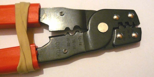
Crimping connectors onto wires requires the right tool, and the most important for this task is – surprise – the crimping pliers. These pliers press the crimping wings of the connector into each other, a task made much easier on the non-ratcheting pliers if you use a rubber band to hold the jaws of the crimping pliers open just enough to hold a crimp connector.

The general theory for crimping all types of connectors is to strip a little bit of insulation off the wire. Then, put the connector into a suitably sized space in the jaws, insert the wire, and crimp it down. For non-ratcheting pliers, it’s suggested the connector be re-crimped with the next smallest hole in the jaws.

There are a few connector-specific tips for the most common connector types, too. Dupont connectors – those flat, black connectors with a 0.1″ pitch – go together like you think they would, but for larger connectors – VH and XH-style – it’s important to use the right wire gauge and not to squish the square female part of the connector.

Advanced Not-Reading Technology

Yesterday, there was a Hackaday post for a Kickstarter campaign. Because we force everyone to read every Hackaday post, there were some complaints and suggestions that we flag posts about Kickstarter campaigns. The most obvious solution to this problem of forcing people to read what they don’t want to read would be a UserScript or browser extension that automatically removes posts with objectionable tags.

It took 12 hours for [Daniel Ward] to lift you up to salvation, ending the inexorable toil you have all suffered under the thumb of idiotic and incompetent Hackaday editors.

[Daniel] wrote a UserScript for GreaseMonkey or TamperMonkey that looks at the tags for each and every Hackaday post. If a tag matches, “crowd-funding”, “crowdfunding”, or “kickstarter”, the post is removed from your browser.

It’s an astonishing advancement in state of the art, “not reading what you don’t want to read” technology. Bards and troubadours will sing of this day for years. Philosophers and theologians are citing this as evidence of something they’re calling, ‘free will.’ We don’t know who [Will] is, but at least he’s free now.

If that’s not enough, [RoGeorge] came up with an astonishing twist on this life-changing technology. By adding, ‘Arduino’ to the blacklisted tags, all posts tagged ‘Arduino’ are also removed. This can, of course, be extended to any tag. Imagine; a world where you don’t have to read what you don’t want to read. A futuristic utopia. Astounding.

3D Printed Pogo Pin Programmer

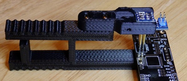
The new hotness for Internet of Things hardware is the ESP8266. Alone it can connect to a WiFi network, but it doesn’t really have a lot of output options. Paired with an ATMega, and you really have something. That’s the philosophy behind the WIOT board, and when [Chris] was assembling these boards, he needed a way to flash firmware. The board has an unpopulated ISP header from the assembler, so pogo pins are the answer. How do you make a pogo pin jig? With a 3D printer, of course.

The ISP header wasn’t populated to give the board a slim profile, but this means a jig of sorts would be needed to program the WIOT. The first attempt was buying a few pogo pin adapters from Tindie, but this was terribly uncomfortable to hold while the board was being programmed.

To fix this problem, a small clip device was rigged up, printed out, and used for programming. Interestingly, this clip has a very deep throat, and a few holes used for bolting on a separate programmer. This shows a lot of forward thinking: the programmer can be reused for different boards with completely different layouts and programmers. If the next revision of the WIOT needs a JTAG header to program the micro, the problem of programming it is already covered.

Automated Die Testing

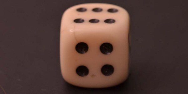
Are the contents of a Crown Royal bag fair? No, they never are. What about dice? In a quest for good randomness, [Apo] designed and built an automated die tester. Not only does it shake the die up, it captures images so real, actual statistics can be done on each individual die.

The setup is a n acrylic box made with BoxMaker attached to a 3D printed adapter for a stepper motor shaft. Randomizing the die happens exactly like you think it would: a stepper shakes the box, and a camera underneath takes a picture. With a bit of computer vision, this image can be translated into a number, ready for the statistics package of your choice.

There were only 559 rolls before the 3D printed mess of duck tape fell apart, but a test of the distribution revealed this die to have a 92% probability that it is fair. That’s not good.

Creating a cheating die is much more interesting, and to find out if he could do it, [Apo] stuck a die in an oven at 100° C for a few minutes. Surprisingly, the fairness of the die got better, suggesting it’s possible to correct an un-fair die. Putting it back in the oven after that threw the fairness out of the window but there was still no visual difference between this modified die and the original stock die.

More Power For Raspberry Pi USB Ports

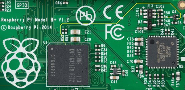
Since the Raspberry Pi 2 was released, everyone building RetroPi emulators has been graced with four USB ports. For those of us doing useful stuff with the Pi, those ports are a little anemic: you can’t plug in a webcam and a WiFi module at the same time without suffering CPU brownouts. The maximum current all USB peripherals can draw from the USB port is 600mA. By changing a value in the /boot/config.txt file, this current limit can be increased to 1.2A for all four ports.

Pisquare
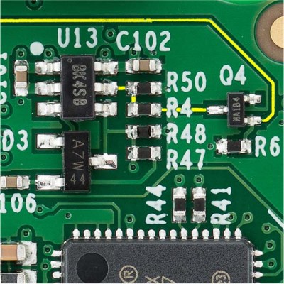
The yellow line traces the signal from the GPIO to the USB power switch.

Because the USB current limit is set in software, there must be a few bits of hardware that do the actual work. Tucked away below the right hand of the GPIO header is the hardware that does exactly that. It’s an AP2253 current-limited power switch (PDF), and the current is adjustable by tying a resistor to pin 5 on the chip.

Pin 5 on the AP2253 is connected to two resistors. One resistor goes directly to a ground plane, while the other is switched through a FET. The gate of this FET goes to another resistor, and when a GPIO pin is high, these resistors are wired in parallel. This means the resistance is halved when the GPIO pin is high, doubling the current limiting circuit in the AP2253.

This setup provides a relatively easy mod to increase the current limiting of the USB ports so they can provide 4x500mA, meeting the USB spec. The AP2253 power switch’s current limiting can be set by a single resistor, anywhere from 10kΩ to 232kΩ. By removing R50 and R4, and replacing R50 with a 10kΩ resistor, the current limiting of the AP2253 switch will be set to its maximum, 2.1A. Divide that by four, and you have 500mA per port, just like every other computer on the planet.

There is a reason the Raspberry Pi foundation set the current limiting of the USB ports so low. The Pi was originally intended to run off of a micro USB phone charger. There aren’t many phone chargers out there that will supply more than 1A, and the CPU and related peripherals will take half of that. If you’re going to change the /boot/config.txt file, you’re going to need a beefy power supply. Increasing the current limiting of the USB ports to 2A will require an even bigger, beefier supply.