Using An AVR As An RFID Tag

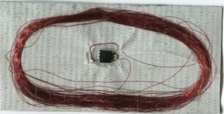
A few years ago, [Beth] came up with the idea of using an AVR as an RFID tag. She’s gotten sidetracked with a few other projects in the meantime but her idea has surfaced again, this time as a duct tape RFID tag. The build is just four components: 0.1 µF and 1 nF capacitors, an ATtiny85 microcontroller, and 100 turns of 40 AWG magnet wire, all soldered together and placed on a duct tape substrate.

Like most RFID tags, the power is drawn from the reader through the coil, but even in low power versions the ATtiny is only rated down to 1.8 Volts. Since the microcontroller is only getting about 1 Volt from the coil, the clock oscillator of the ATtiny won’t work. This isn’t a problem in this build, because the coil is connected to the the clock input – the 125 kHz coming off the reader provides the clock. Very clever.

Of course, the microcontroller is going to need some firmware to send some bits to the reader, so she used the AVRFID firmware (check out the comments in the source for a great walkthrough) to transmit under the HID protocol, itself a derivative of [Beth]’s earlier work with the EM4102 protocol.

Not only are we impressed with this hack, we’re amazed [Beth] is still perfecting her work more than two years after her first post on the subject. That’s dedication and unbridled cleverness.

Via adafruit
A Computer-controlled Shutter For Polaroid Packfilm Cameras

[Georg] wanted to modify his old Polaroid land camera so he could have control over the exposure time. The resulting project is a neat hack, if we say so ourselves.

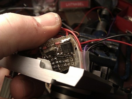
The stock electronics in Polaroid 100-series Packfilm cameras were a simple analog computer that integrates current through a light-sensitive resistor. This is a simple, low tech way to make sure the exposure time is correct. The usual mod would be to replace photoresistor with a potentiometer, but [Georg] had little success with this modification. After tearing the old hack out of the camera, [Georg] replaced the ancient electronics with a a PIC microcontroller, and is now able to control the shutter in increments down to 1/512th of a second.

Shutter timing is read by a PIC12F629 μC with a BCD encoder. [Georg] kept the shutter magnet setup, and also added a ‘BULB’ routine that holds the shutter open as long as the button is held down. The test photos are quite nice, even if from a 1960s Polaroid Land Camera. Check out the video of [Georg] running though the shutter settings after the break.

Continue reading “A Computer-controlled Shutter For Polaroid Packfilm Cameras”

Ollie The Socially Awkward Autonomous Blimp

[Pritika] is a user experience design student who just finished up an autonomous blimp project designed to react to voices and communicate, “his friendliness and eagerness to be noticed.”

The instructable [Pritika] posted goes through the build – a 850mAh LiPo battery powers an Arduino Pro Mini, which controls two 3.6 gram servos. While not much in the way of electronics, the real beauty behind this build is the implementation. From watching the video of Ollie interacting with people, we’re pretty sure [Pritika] met her objective of making her pet blimp friendly and unobtrusive.

With quadrocopters getting so much attention as of late, it’s interesting to see development in lighter-than-air robotics. Our back of the envelope math (which is almost certainly wrong) tells us that Ollie’s ‘body’ can lift 60 grams when filled with Helium, and double that with Hydrogen. While this isn’t much lifting capacity, it’s not inconceivable that a slightly larger blimp could have more sensors or a live video feed, especially considering the 16 gram ornithopter we covered last year.

Check out a video of Ollie after the jump.

Continue reading “Ollie The Socially Awkward Autonomous Blimp”

Destroying An Arduino’s EEPROM

We’ve seen projects test the lifespan of an EEPROM before, but these projects have only tested discrete EEPROM chips. [John] at tronixstuff had a different idea and set out to test the internal EEPROM of an ATmega328.

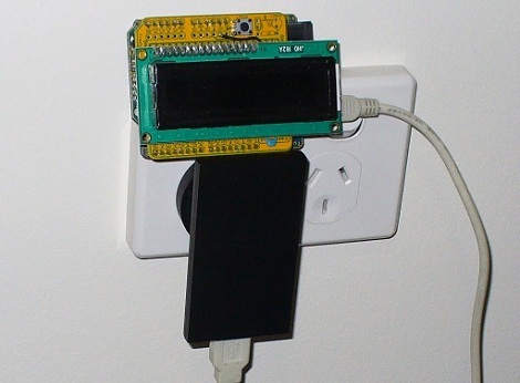
[John]’s build is just an Arduino and LCD shield that writes the number 170 to memory on one pass, and the number 85 on the next pass. Because these numbers are 10101010 and 01010101 in binary, each bit is flipped flipped once each run. We think this might be better than writing 0xFF for every run – hackaday readers are welcomed to comment on this implementation. The Arduino was plugged into a wall wart and sat, “behind a couch for a couple of months.” The EEPROM saw it’s first write error after 47 days and 1,230,163 cycles. This is an order of magnitude better than the spec on the atmel datasheet, but similar to the results of similar experiments.

We covered a similar project, the Flash Destroyer, last year, but that tested an external EEPROM, and not the internal memory of a microcontroller.

Check out the hugely abridged video of the EEPROM Killer after the break.

Continue reading “Destroying An Arduino’s EEPROM”

Optimizing Code For PWM Efficiency

For some projects, it’s okay to have a microcontroller twiddling it’s thumbs most of the time. When a project requires the cpu to do just one thing over and over, there’s no loss with inefficient code – it either works or it doesn’t. However, if a project requires a microcontroller to do several things at once, like reading sensors, dimming LEDs, and writing serial data out, cpu utilization can become an issue. [Robert] wasn’t happy with the code he used to control a string of LEDs, so he rewrote his code. With the old implementation, [Robert]’s code used 60% of the cpu time. With the new and improved code, the cpu was only busy 8% of the time.

The code works by using a hardware timer to trigger an interrupt. After calculating the next time it should run again, and changing the state of the data line, the code just sits quietly until it’s needed again.

It’s not a pretty hack, or even one you can hold in your hands, but [Robert]’s determination in getting a μC to do what he wants is admirable.

Emulating A Marching Band With Wearable Instruments

[Scott] is a design and technology master’s student who just came up with The Imaginary Marching Band – virtual band instruments you can wear on your hand.

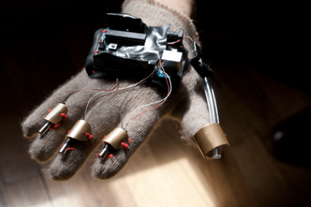
Taking inspiration from Minority Report and the NES Power Glove, the system is able to emulate 6 instruments at this point – A trumpet, trombone, tuba, snare drum, bass drum, and cymbals. The glove itself reads data from a variety of sensors and passes that onto an Arduino Uno which sends serial data back to a computer. This data is then parsed by a Serial – MIDI converter, and can then be played back through a sampler, synthesizer or piped into your sequencer of choice. Happily, [Scott] will be designing custom PCBs for his gloves to cut down on space and weight, and he’ll also be making his project open-source eventually.

[Scott] has a kickstarter page for his project, and so far he’s been on track towards getting this project funded. Check out a demo after the break.

Continue reading “Emulating A Marching Band With Wearable Instruments”

Adding MIDI To A Very Old Drum Machine

Long before drum machines played samples from an SD card or EPROM, drum sounds were analog – just filtered waveforms and noise. To the modern eye, these are very primitive machines, but for [Andrew], they’re the inspiration for this brilliant hack.

[Andrew] took a Roland CR-68 drum machine from 1978 and added MIDI input with the help of a PIC microcontroller. Not wanting to modify the look of the machine, [Andrew] programmed the PIC to watch the START/STOP button when the the unit is powered on. If the button is held down, the PIC enters it’s programming mode, where the sounds from the CR-68 can be mapped to an individual note on a MIDI controller. There’s no mention if the TRIGGER IN is queried by the PIC to modify the tempo of the preset patterns, but we assume that would be a relatively trivial implementation. Still, very impressive for a machine made 4 years before MIDI.

We love [Andrew]’s work, and we’re happy for any future owner that he documented how to use his device (and cleverly taped that to the bottom of the drum machine). It’s very nice to see old drum machines being used for more than doorstops after their samples have been recorded. Check out the video of [Andrew]’s walk through after the break.

Continue reading “Adding MIDI To A Very Old Drum Machine”