VGA Graphics Card In 74xx Logic

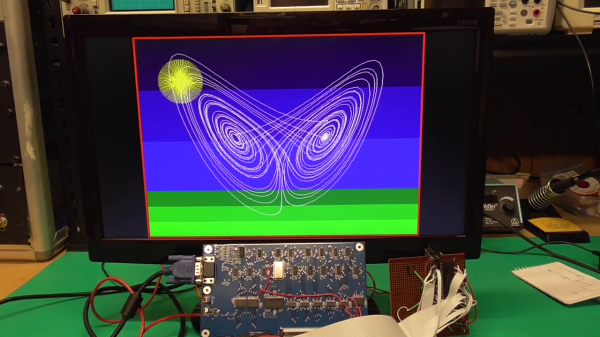
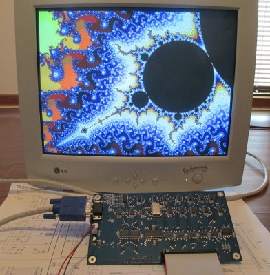
Feeling nostalgic we presume, [Glen Kleinschmidt] set out to build a 640x480x64 VGA controller card from discrete logic chips. If we ignore the 512Kx8 Cypress SRAM video memory, he succeeds, too — and on a very readable, single page A3 schematic. The goal is to interface some of his older 8-bit machines, like the TRS-80 Model 1 and the BBC Micro, but for now he’s running a demo using a 20+ year old PIC16F877 micro.

[Glen] provides all the schematics, Gerbers, and C source code on his website should you be inclined to reproduce one for yourself. He has three versions in the works, with various capabilities (there’s a table on his website). As an alternative, one could always use an FPGA or a custom-built chip such as the SSD1963 to generate video for these micros, but sometimes the urge to go retro is too great to resist. We get the feeling that for [Glen], this is a project unto itself, and being able to interface it to his 8-bit computers is just a convenient excuse.

This isn’t [Glen]’s first retro project, either. Check out his analog computer “bouncing ball” project we covered back in 2017. Have you struggled with the build vs. buy decision, and how do you decide?

Continue reading “VGA Graphics Card In 74xx Logic”

Shipping A CRT: Lessons Learned

Old CRT computer enthusiast [x86VileR] recently tracked down an IBM 5153 monitor for which he had been searching several years. Unfortunately shipping a heavy glass CRT isn’t easy. In fact, it took [VileR] three tries to get a functioning monitor delivered intact and working. The first one seemed reasonably protected in its packaging, but arrived so banged up that the CRT had become dislodged inside the monitor and the neck broke off! The second attempt was packaged even better, and he was sure it would arrive problem-free. Alas, it too arrived all banged up and broken.

This one clearly had superior packaging, so I find it difficult to account for this truly stupendous level of damage. The most promising theory is that several people jumped on it simultaneously, just before the delivery truck ran it over. As my friend put it, it would’ve arrived in better shape if he had just smashed it himself before boxing it up.

Double-boxing appears to be the answer, although it might result in a box too large to ship depending on your courier’s rules. Short of building custom wooden crates, do you have any packing tips for shipping heavy and fragile items? Thanks to [J.R. Dahlman] for sending us the tip.

Wireless MicroPython Programming With Thonny

I’ve been playing with a few MicroPython projects recently on several different embedded platforms, including a couple of ESP32 WiFi modules. There are various ways to program these modules:

  • Use a serial terminal and ampy (maintained by [devxpy] since being dropped by Adafruit in 2018).
  • If you use Pycom boards or WiFy firmware, there are the pymakr plugins for Atom and Visual Studio.
  • If you prefer the command-line like me, there is rshell by one of the top MicroPython contributors [Dave Hylands].

For over a year, I have been quite happy with rshell until I started working on these wireless nodes. Being lazy, I want to tinker with my ESP32 modules from the sofa, not drag my laptop into the kitchen or balcony to plug up a USB cable. Can’t I work with them wirelessly?

Well, you can use WebREPL. While its functional, it just didn’t strike my fancy for some reason. [Elliot] mentioned in a recent podcast that he’s using telnet to access his wireless nodes, but he’s using esp-link on an ESP8266, which means throwing another chip into the mix.

The Thonny IDE

I had all but given up when by chance I saw this video on the Dronebot Workshop channel about running MicroPython on the new Raspberry Pi Pico boards. Bill was using Thonny, a Python IDE that is popular in the education community. Thonny was introduced in 2015 by Aivar Annamaa of the University of Tartu in Estonia. Thonny was designed to address common issues observed during six years of teaching Python programming classes to beginners. If you read about the project and its development, you’ll see that he’s put a lot of effort into making Thonny, and it shows.

Leaning about Thonny got me curious, and after a little digging I discovered that it has WebREPL support for MicroPython right out-of-the-box. Although this is a new feature and classified as experimental, I found it reasonably stable to use and more than adequate for home lab use. Continue reading “Wireless MicroPython Programming With Thonny”

ASCII Schematic Diagrams

We wondered recently about those crude ASCII schematics you see in some documentation — are there any dedicated schematic-focused tools to draw them, or are they just hand-crafted using various ASCII-art drawing tools? To our surprise, there is such a tool. It is called AACircuit and was developed by [Andreas Weber]. It has a history going back to 2001 when it was first introduced as ASCIIPaint. Be forewarned, however, the quality of the code may be questionable. According to the notes on [Andy]’s GitHub repository:

WARNING: a lot of spaghetti code ahead

This code was created in 2001-2004 when I taught Borland Delphi 3 to myself. It contains many, many global variables, unstructured and undocumented procedural code and bad variable names.

If you don’t want to wrestle with old and sketchy object-oriented Pascal code, you’re in luck. [Chaos Ordered] has made a Pythonized version which you can get from his GitHub repository. We tried it out and got it working on Ubuntu in short order (after wrestling with a pycairo dependencies). This might not be everyone’s cup of tea, but it has some uses now and then. While we wouldn’t want to document a computer motherboard with ASCII schematics, it’s great for a quick-and-dirty circuit diagrams.

Not exactly schematics, but [Duckman] has some Arduino pinout diagrams he made using ASCII-art. These could be useful when pasted into source code as comments, documenting the pinouts for your project.

Do you recommend any tools for making ASCII schematics, or this just a waste of time?

CubeSat For Under $1000?

Want to build your own CubeSat but have been put off by the price? There may be a solution in the works — [RG Sat] has challenged himself to design and build one for less than $1,000. (Video, embedded below.)

He begins by doing a survey of available low-cost options in the first video, and finds there isn’t a complete package for less than $10,000. By the time you added all necessary “options”, the final tally would probably be well over $20,000.

His idea isn’t just a pipe dream, either. In the the fifteen months since he began the project, [RG Sat] has designed and built the avionics and electrical power system circuit boards, and is currently testing his sun tracker design. Software is written in Rust, just because he wants to learn something new. You can check out the hardware and software design files on the project’s GitHub repositories, if you are inclined to build one yourself.

[RG Sat] lays out a compelling case, but we wonder if there’s a major gotcha lurking in the dark somewhere. In fact, [RG Sat] himself asks the question, “where do these high costs come from?” Our first instinct is to point the finger at qualifying parts for space and/or testing. But if you don’t care about satellite longevity or failure rates, then maybe [RG Sat] is onto something here.

Stepping back and looking at the big picture, however, the price of a CubeSat can be a drop in the bucket when compared to the launch costs, unless you’ve got a free ride. Is hardware the best place to focus cost reduction efforts?  Regardless, [RG Sat]’s project is bound to provide interesting and useful results whether he succeeds in his goal or confirms that indeed you need $10,000 to build a CubeSat. We’ll be following his progress with interest.

We’ve written about open source CubeSats before, and also a port-mortem analysis of a failed mission that contains some good lessons. Thanks to [Jeremy Grosser] for the tip.


Small Open Source Vehicle Hacking Platform

[Florian] and his engineering team at Munich-based bmc::labs has developed a clever set of prototyping boards for vehicle hacking and rapid product development, collectively called the bmc::board or bmc::mini. These stackable development boards were initially designed for in-house use. The team took a general purpose approach to the design so the boards could be used across a wide range of projects, and they should be useful to anyone in the field. [Florian] decided to release the boards to the community as open-source and certified by OSHWA (Open Source Hardware Association).

There are four boards currently defined, with several more in the works:

  • mini::base — Main microcontroller board, STM32F103-based
  • mini::out — I/O board with CAN bus, JTAG, etc.
  • mini:: grid — RF board providing GPS and GSM capability
  • mini::pit — local wireless connectivity, WiFi and Bluetooth, and 2nd CAN bus

At 54 x 42.5 mm, these boards are pretty small; a form-factor they describe as “exactly half a credit card”. We like the Wurth WR-MM family of stacking connectors they are using, and the symmetrical pinout means you can rotate the cards as needed. But at first glance, these thru-hole connectors seem to limit the stack to just two boards, although maybe they plan move to an SMT flavor of the connector in future designs permitting taller stacks.

If you’re into vehicle electronics and/or vehicle hacking, definitely take a look at these. You can check out [Florian]’s bmc::board Hackaday.io project page and the team’s GitHub repository for more details. Here’s another project by team member [Sebastian] using one of the future bmc::bike modules to eavesdrop on ECU communications, where he sensibly advises the reader “First, pull over and get off the bike. Never hack a two-wheeled vehicle while riding it!”.

No discussion of vehicle CAN bus tools should omit the work of Craig Smith, who literally wrote the book on hacking your car, and whose talk along with Hackaday’s own Eric Evenchick of CANtact fame we covered back in 2016. [Florian] has started a CrowdSupply campaign where you can see some more details of this project and a short promotional video.

Forth Module The Size Of A Stick Of Gum

Australian engineer [John Catsoulis] developed a small module called the Scamp2 dedicated to running Forth. The focus of his Udamonic project was not only to highlight Forth, but to make a module which was easy to use and doesn’t require any IDE on your computer. According to the website, these modules have found their niche in education as well as rapid prototyping for product development. His site has some good resources, including several Scamp/Forth example applications such as a model train controller or adding a real-time clock module.

The core of the module is a Microchip PIC24F64GB202 MCU with 64K Flash and 8K RAM. Of this, Forth takes up only 20K of Flash and 2K of RAM. [John] is using FlashForth, a version of Forth which came from [Mikael Nordman] at the University of Queensland almost ten years ago. FlashForth has been implemented on a wide variety of PIC and AVR ATmega processors and has apparently developed quite a following in Australia and elsewhere.

We estimate from the photo that the Scamp is about 80 mm long, just slightly longer than a standard piece of MIL-A-A-20175A Type II chewing gum ( 73 mm ). You can use it as-is, or with the header pins installed, the Scamp can be plugged into a breadboard for easy hacking. Regarding the interfacing of Scamp to other equipment, [John] says “Writing software to use other hardware is very easy, and fun.” We like his attitude.

Here is some more information from his Hackaday.io project page, and he also has a Tindie site. If you want a good overview of using Forth in embedded systems, check out Forth: The Hacker’s Language by our own Forth-guru [Elliot Williams]. Thanks to [Stephen Walters] for sending in the tip.

Continue reading “Forth Module The Size Of A Stick Of Gum”