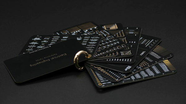
What started as business cards for [Nerdonic]’s engineering clients unexpectedly expanded into a project in its own right. A CheatKard set consists of seven electronics cheat sheets made in the style of PCB rulers. Sized at 80 mm x 50 mm, they should fit in your business card holder or wallet regardless of the standard in your country. Alternatively, the set can be held together with a small ring in the top corner. The cards are made from fiberglass PCB stock, 0.6 mm thick with gold plating and matte black solder mask. The stackup goes like so:
- Cover
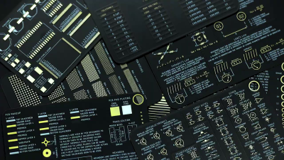
- Measurements
- Schematic Symbols
- Component Values
- Footprints, SMD 1
- Footprints, SMD 2
- PCB Design
- Laws and Theory
Even before shipping this electronics set, [Nerdonic] has already been asked to make sets of CheatKards for other fields, such as photography, chemistry, antenna design, mathematics, etc. While these aren’t as comprehensive as the Pocket Ref book from years gone by, we like a good cheat sheet. If you want to get a set, check out [Nerdonic]’s Kickstarter project which was funded within hours of going live, and see the short video clip below the break. He also makes a pledge to plant one tree in the Amazon rainforest for each set he sells.
Do you have any favorite cheat sheets or cheat sheet making techniques? Do you prefer your cheat sheets to be physical or stored on your computer? Share your comments down below.