PnPAssist: A “Smart” Build Platform For Manual PCB Assembly

Open source pick and place machines have come a long way in the past years, but are not necessarily worth the setup time and machine cost if you are only building a few PCBs at a time. [Nuri Erginer] found himself in this situation regularly, so he created PnPAssist, a “smart” build platform to speed up manual PCB assembly. Video after the break.

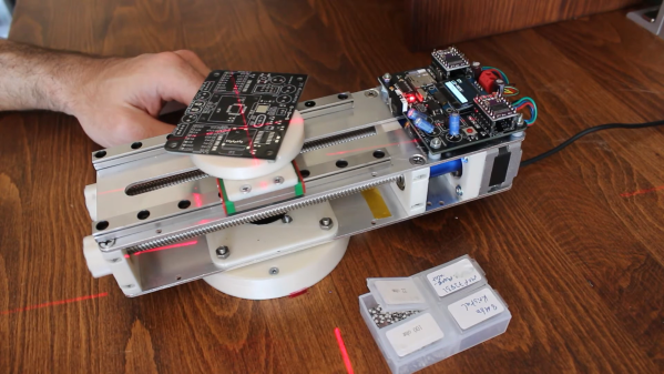
The PnP assist consists of a small circular platform that can automatically translate and rotate to place the current footprint in the middle of the platform, right in the center of your microscope’s view, and a laser crosshair. The entire device can also rotate freely on its base to avoid contorting your arm to match the footprint orientation. Just export the PnP file from your favorite PCB design software, load it on a micro SD card, plug it into the PnPAssist, and start assembling. The relevant component information is displayed on a small OLED display right on the machine. [Nuri] has also created a component organizing tray that will indicate the correct compartment with an RGB LED.

Below the build platform, a 3D printed gear is in contact with a pair of parallel lead screws driven by stepper motors. The relative motion of the lead screws allows the platform to rotate, translate, or both. This arrangement also means the machine is a lot more compact than a conventional XY-table and can be packed away when not in use. The base is held firmly in place on the workbench with a set of suction cups or screws. Power is provided through the fixed base using a slip-ring, so there are no cables to twist up as you spin the machine around. Continue reading “PnPAssist: A “Smart” Build Platform For Manual PCB Assembly”

Tardygrade Walker Is A Lesson In 3D Printed Design

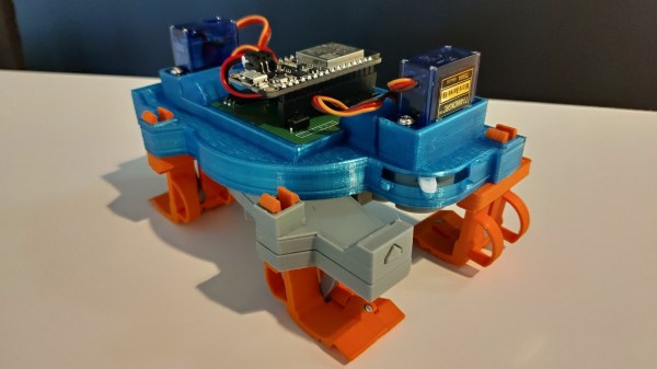
The ability to quickly create complex parts with 3D printers has created a platform to show off mechanical design skills. This is true in the case of [Dejan Ristic]’s capable little Tardygrade walking robot, which uses only two servos and a bunch of clever 3D printed parts.

The robot’s chassis is split into two subassemblies, each with a pair of feet on diagonal corners. As one pair of feet lifts the robot, the other section of the robot can rotate before coming back down, allowing the robot to turn. One servo handles the actuation of the feet, while the other rotates the body as required. An ESP32 based controller creates a web server user interface, and power comes from a lipo cell.

The interesting part of this robot is in how [Dejan] designed it for printing and assembly. All the parts can print without support, and in the correct orientation to optimize strength. There are only six screws in the assembly holding the servo and servo horns, while everything else uses snap fits or short pieces of filament. Take a look at the videos after the break to gain some appreciation of the design effort and attention to detail that went into this robot. Even the contact surfaces of the feet were carefully designed for optimum walking over flat surfaces and small obstacles.

This reminds us of [gzumwalt]’s little 3D printed creations, like the fridge crawler and mechanical edge-avoiding robot.

Rover Uses Different Kind Of Tracks

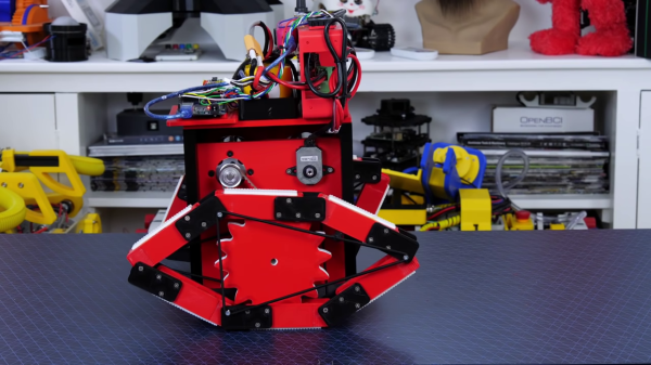
Tracked robots usually require at least two wheels inside to work properly. However, [James Bruton] discovered a curious tractor design from the 1940s, the Fordson Rotaped, which only uses a single sprocket wheel inside each track. Being [James], he built a self-balancing robot around the rotaped concept.

Instead of a lot of short track sections, the Rotaped uses six long sections of track, about the same length as the wheel’s diameter. To keep the track on the wheel, a series of chains or an oval frame is used on the inside of the track.

As is usual for [James]’ projects, most of the mechanical parts are 3D printed. To hold the tracks in place, he stretches a bungee cord loop around three points on each side of the track. To make things more interesting, he made the robot balanced on the tracks. This took a bit of PID tuning to get working without oscillations, since the wheels experience a slight cogging effect inside the tracks. The wheels are driven by a pair of brushless motors with O-Drive controllers. The balancing is handled by an Arduino Mega, which reads processed position values from an Arduino Pro Mini connected to an MPU6050 IMU.

This might be a viable alternative to conventional tracks for certain applications, and the reduced part count is certainly an advantage. Let us know in the comments if it spawns any ideas. [James] has previously built another tracked rover, which uses flexible 3D printed track sections. By far, the biggest 3D printed tracked vehicle we’ve seen was [Ivan Miranda]’s ridable tank.

Continue reading “Rover Uses Different Kind Of Tracks”

ZeroBug: From Simulation To Smooth Walking

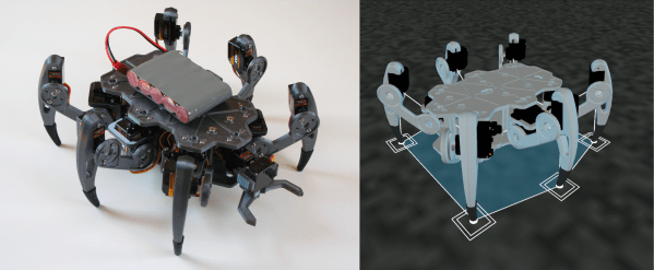
Thanks to 3D printing and cheap hobby servos, building you’re own small walking robot is not particularly difficult, but getting them to walk smoothly can be an entirely different story. Knowing this from experience, [Max.K] tackled the software side first by creating a virtual simulation of his ZeroBug hexapod, before building it.

Learning from his previous experience building a quadruped, ZeroBug started life in Processing as a simple stick figure, which gradually increased in complexity as [Max.K] figured out how to make it walk properly. He first developed the required movement sequence for the tip of each leg, and then added joints and calculated the actuator movements using reverse kinematics. Using the results of the simulations, he designed the mechanics and pulled it back into the simulation for final validation.

Each leg uses three micro servos which are controlled by an STM32F103 on a custom PCB, which handles all the motion calculations. It receives commands over UART from a python script running on a Raspberry Pi Zero. This allows for user control over a web interface using WiFi, or from a gamepad using a Bluetooth connection. [Max.K] also added a pincer to the front to allow it to interact with its environment. Video after the break.

The final product moves a lot smoother than most other servo-driven hexapods we’ve seen, and the entire project is well documented. The electronics and software are available on GitHub and the mechanics on Thingiverse.

Continue reading “ZeroBug: From Simulation To Smooth Walking”

Giving Control Of A Smartphone Robot To A Raspberry Pi

Most gadgets that interface with smartphones have a rather short lifespan and inevitably end up as E-waste. Unless hackers give them a second life, as is the case with the Romo, a little smartphone-controlled robot. [David Goeken] has successfully reverse-engineered the communication protocol to allow the Romo to controlled Raspberry Pi (or microcontroller)

The Romo was a little iPhone-controlled robot brought to market with a Kickstarter campaign back in 2013. It originally used the audio jack from the iPhone for the control interface, but was quickly followed by an updated version that used iPhone 4’s 30 pin connector and later the Lightning port. Romotive, the company behind Romo, eventually went out of business, but fortunately, they open-sourced the IOS app and the firmware. This has led to a few third-party apps currently on the app store.

[David] wanted to use other hardware for control, so he set about reverse-engineering the protocol using the open-source software and a logic analyzer. Unsurprisingly, it uses a serial interface to send and receive commands, with two additional pins to detect the connection and wake up the Romo. After breaking out the interface header on the board, he was able to modify the Romo to mount a Raspberry Pi Zero, and power it using the internal battery.

[David] has not made his code public yet, but it sounds like he plans to. It looks like Romo’s can be a fun little experimentation platform, and they can be found for cheap on eBay. We covered another cool Romo hack back in 2014, which used a projector and vision system to create a Mariokart-like game.  For a completely open-source smartphone robot, check out the OpenBot.

3D Printed CNC Knee Mill

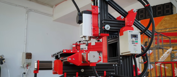
CNC mills will never match real heavy metal mills on hard materials, but that won’t stop people from pushing the limits of these DIY machines. One of the usual suspects, [Ivan Miranda] is at it again, this time building a knee mill from aluminum extrusions and 3D printed fittings. (Video after the break.)

Most DIY CNC milling machines we see use a gantry arrangement, where the bed is fixed while everything else moves around it. On most commercial metal milling machines, the table is the moving part, and are known as knee mills. In the case of [Ivan]’s mill, the table can move 187 mm on the X-axis and 163 mm on the Y-axis. The 1.5 kW spindle can move 87 mm in the Z-axis. All axes slide on linear rails and are driven by large stepper motors using ball screws. The table can also be adjusted in the Z-direction to accept larger workpieces, and the spindle can be tilted to mill at an angle.

To machine metal as [Ivan] intended, rigidity is the name of the game, and 3D printed parts and aluminum extrusion will never be as rigid as heavy blocks of steel. He says claims that the wobble seen on the video is due to the uneven table on which the mill was standing. Of course, a wobbly base won’t be doing him any favors. [Ivan] also had some trouble with earthing on the spindle. He nearly set his workshop on fire when he didn’t notice tiny sparks between the cutter and aluminum workpiece while he was cooling it with isopropyl alcohol. This was solved with the addition of the grounding wire.

While the machine does have limitations, it does look like it can machine functional metal parts. It could even machine metal upgrades for its 3D printed components. One possible way to improve rigidity would be to cast the frame in concrete. [Ivan] has built several other workshop tools, including a massive 3D printer and a camera crane. Continue reading “3D Printed CNC Knee Mill”

Wing Can Expand To Fly Really Slow For Short Take-Off And Landing

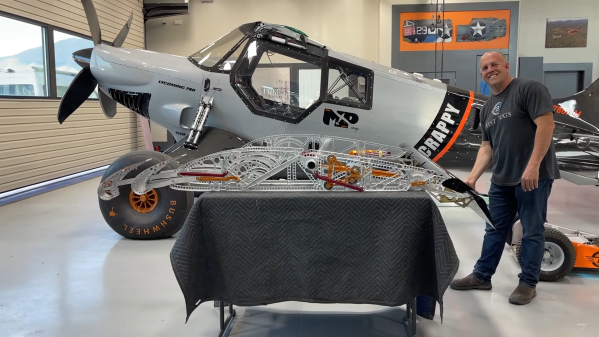
[Mike Patey] had made a name for himself by building high-performance experimental aircraft. In his latest project, he added a transforming wing that can extend its chord by up to 16 inches for low speed and high angle of attack performance.

The aircraft in question, a bush plane named Scrappy, has been attracting attention long before [Mike] even started building the wings. Designed for extremely short take-off and landing (STOL) performance, only some sections of the fuselage frame remain from the original Carbon Cub kit. The wings are custom designed and feature double slats on the leading edge, combined with large flaps and drooping ailerons on the trailing edge. The slats form an almost seamless part of the wing for normal flying, but can expand using a series of linkages integrated into each precision machine wing rib. Making extensive use of CFD simulations, the slats were designed to keep the center-of-lift close to the center of the wing, even with 50 degrees of flaps. Without the slats, the pilot would need to use almost all the elevator authority to counteract the flaps and keep the aircraft’s nose up.

Leading-edge slats have been around since before WW2, but you don’t see them used in pairs like this. Aircraft like Scrappy will never be commercially viable, but innovation by people like [Mike] drives aviation forward. [Mike]’s previous project plane, Draco, was a large turboprop bush plane built around a PZL-104 Wilga. Sadly it was destroyed during an ill-considered take-off in 2019, but [Mike] is already planning its successor, Draco-X. Continue reading “Wing Can Expand To Fly Really Slow For Short Take-Off And Landing”