Microstepping A PCB Motor

Over the last 2 years [Carl Bujega] has made a name for himself with his PCB motor designs. His latest adventure is to turn it into a stepper motor by adding position control with microstepping.

The NEMA stepper motors most of us know are synchronous stepper motors, while [Carl]’s design is a permanent magnet design. It uses four coils on the stator, and two permanent magnets on the rotor/dial. By varying the current through each of the four poles with a stepper driver (microstepping), the position of the rotor should theoretically be controllable with good resolution. Unfortunately, this was easier said than done. He achieved position control, but it kept skipping steps in certain positions.

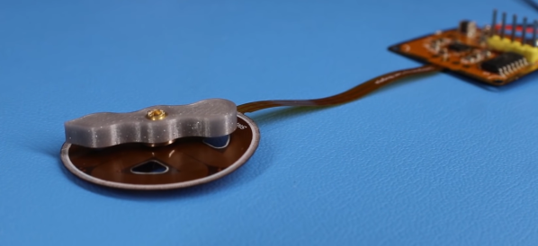
The motor and controller consist of a single flexible PCB, to reduce the layer spacing and increase the coils’ magnetic field strength. However, this created other problems, since the motor shaft didn’t have a solid mounting point, and the PCB flexed as the stator coils were energized. Soldering the controller was also a problem, as the through-hole headers ripped out easily and the PCB bulged while reflowing on a hot plate, in one case even popping off components. [Carl] eventually mounted one of the PCB motors inside a 3D printed frame to rigidly constrain all the motor components, but it still suffered from missed steps. Any suggestions for fixing the problem? Drop them in the comments below.

Like his other PCB motors, the torque is very low, but should be suitable for gauges or clocks. A PCB clock with an integrated motor would be pretty cool to have on the workshop wall.

The TMC2300 stepper driver [Carl] used belongs to the same family of drivers that enable silent stepping for 3D printers. We’ve covered a few of [Carl]’s PCB actuator adventures, from his original design to linear actuators and a flexible POV display.

Continue reading “Microstepping A PCB Motor”

A Walking Rover Destined Explore Your Fridge Door

It’s usually the simple ideas that sprout bigger ones, and this was the case when we saw [gzumwalt]’s single-motor walking robot crawling up a fridge door with magnets on its feet. (Video, embedded below.)

The walking mechanism consists of an inner foot and two outer feet, connected by three sets of rotating linkages, driven by a single geared motor. The feet move in a leapfrog motion, in small enough steps that the center of mass always stays inside the foot area, which keeps it from tipping over. Besides the previously mentioned ability to crawl around on a vertical magnetic surface, it’s also able to crawl over almost any obstacle shorter than its step length. A larger version should also be able to climb stairs.

As shown, this robot can only travel in a straight line, but this could be solved by adding a disc on the bottom of the inner foot to turn the robot when the outer feet are off the surface. Add some microswitch feelers and an Arduino, and it can autonomously explore your fridge without falling off. Maybe we’ll get around to building it ourselves, but be sure to drop us a tip if you beat us to it!

[gzumwalt] is a master of 3D printed devices like a rigid chain and a domino laying robot. The mechanism for this robot was inspired by one design from [thang010146]’s marvelous video library of mechanisms.

Continue reading “A Walking Rover Destined Explore Your Fridge Door”

SLA 3D Printed Vortex Cooled Rocket Engine

3D printing is an incredible tool for prototyping and development, but the properties of the materials can be a limiting factor for functional parts. [Sam Rogers] and colleagues at [AX Technologies] have been testing and developing a small liquid-fueled rocket engine and successfully used vortex cooling to protect a resin 3D printed combustion chamber. (Video, embedded below.)

Vortex cooling works by injecting oxygen into the combustion chamber tangentially, just inside the nozzle of the engine, which creates a cooling, swirling vortex boundary layer along the chamber wall. The oxygen moves to the front end of the combustion chamber where it mixes with the fuel and ignites in the center. This does not protect the nozzle itself, which only lasts a few seconds before becoming unusable. However, thanks to the modular design of the test engine, only the small nozzle section had to be reprinted for every test. While this part could be manufactured using a metal 3D printer, the costs are still very high, especially at this experimental stage. The clear resin parts also allow the combustion observed and more accurate conclusions to be drawn from every test.

This engine intended to be used as a torch igniter for a much larger rocket engine. Fuel is injected into the front of the combustion chamber, where a spark plug is located to ignite the oxygen-fuel mixture. The flow of the oxygen and fuel is controlled by two servo-operated valves connected to a microcontroller, which is mounted with the engine on linear rails. This allows the test engine to move freely, and push against a load cell to measure thrust. The spark is created before the valves are opened to prevent a delayed ignition, which can blow up the engine, and getting the valve sequence and timing correct is critical. Many iterations and destroyed parts later, the [AX Technologies] team achieved successful ignition, with a clear supersonic Mach diamond pattern in the exhaust.

This is just one more example of 3D printing and cheap electronics allowing impressive progress on a limited budget. Another example is [Joe Barnard]’s progress in getting a model rocket to land itself with a solid fuel engine. Companies and organisations have been using 3D printed components in rocket engines for a few years now, and we’ve even seen an open source version.

3D Printed Rigid Chain Mechanism

One of the major advantages of 3D printing is the ability to quickly test and then iterate on mechanical designs. [gzumwalt] does a lot of this, and has recently been working on various versions of a rigid chain mechanism. (Video, embedded below.)

A rigid-chain mechanism is one way of fitting a long beam into a small box. It works similar to a zipper, meshing two separate “chains” with specially teeth designed to form a rigid beam. Due to clearances between the teeth, the beam tends to be a bit floppy. [gzumwalt] made various sizes of the mechanism, and also reduced the clearances on later versions to reduce the flop. He also integrated it into a cool “snake in a basket” automaton (second video below) by adding a reversible gearbox and a binary snap-action switch.

One possible use for this type of mechanism is for autonomously assembling long structures in space, as one of the 2017 Hackaday Prize finalist projects, ZBeam, proposed.

[gzumwalt] has not made the files available for download yet, but you can keep and eye on his Instructables pages for updates. He got a number of fascinating 3D printed devices already available, like a domino laying machine or a WiFi controlled rover.

Continue reading “3D Printed Rigid Chain Mechanism”

Slim RGB Matrix Puts LEDs Inside The PCB

Sometimes all that’s required to build something interesting is to put the same old pieces together differently. [Sayantan Pal] did this for the humble RGB LED matrix, creating an extra-thin version by recessing WS2812b NeoPixel LEDs inside a PCB.

The popular WS2812B is 1.6 mm in height, which happens to be the most commonly used PCB thickness. Using EasyEDA, [Sayantan] designed a 8×8 matrix with modified WS2812B footprints. A slightly undersized cutout was added to create a friction-fit for the LEDs, and the pads were moved to the back side of the panel just outside the cutout, and their assignment were flipped. The PCB is assembled face down, and all the pads are soldered by hand. Unfortunately this creates rather large solder bridges which slightly increases the overall thickness of the panel, and is probably also unsuitable for production with conventional pick-and-place assembly.

We’ve seen some similar methods with PCB assemblies that use layered PCBs. Manufacturers are starting to even embed components inside multilayer PCBs.

Tiny Chain-Link Fence Made With Hand-Cranked Brilliance

Chain link fences are woven with a mechanism that is almost hypnotic to watch, so [Levsha] decided to build his own tiny hand-crank tabletop version to make tiny copper wire fences.

Chain link consist of a series of wires bent and woven in a zigzag pattern. The zigzag bends are made by winding the wire around a rotating flat plate inside a stationary tube with a spiral slot in the side to keep the spacing of the bends consistent. [Levsha]’s version is roughly 1/10 scale of the real thing, and only does the bending and winding parts. Linking the bent wire together is up to the operator. All the components were machined on a lathe and CNC router, and beautifully finished and assembled on a wood base. The hardest part was the tube with the spiral slot, which took a few attempts to get right. [Levsha] initially tried to use steel wire, but it was too stiff and caused the winding mechanism to lock up. 0.4 mm copper wire turned out to be the best choice.

Although there is no practical use for this device that we can see, the craftsmanship is excellent, and it is one of those videos that reminds us how badly we want some machine tools.

Fine attention to detail is really what makes videos like this enjoyable to watch. Wee seen a few other such project, like a beautiful scratch-built lathe, or a pneumatic powered drone that can’t fly.

Continue reading “Tiny Chain-Link Fence Made With Hand-Cranked Brilliance”

Diaphragm Air Engine

One of the tricky parts of engineering in the physical world is making machines work with the available resources and manufacturing technologies. [Tom Stanton] has designed and made a couple of air-powered 3D printed engines but always struggled with the problem of air leaking past the 3D-printed pistons. Instead of trying to make an air-tight piston, he added a rubber membrane and a clever valve system to create a diaphragm air engine.

This GIF is worth 115 words

A round rubber diaphragm with a hole in the center creates a seal with the piston at the top of its stroke. A brass sleeve and pin protrude through the diaphragm, and the sleeve seals create a plug with an o-ring, while the pin pushes open a ball which acts as the inlet valve to pressurize an intermediate chamber. As the piston retracts, the ball closes the inlet valve, the outlet valve of the intermediate chamber is opened, forcing the diaphragm to push against the piston. The seal between the piston and diaphragm holds until the piston reaches its bottom position, where the pressurized air is vented past the piston and out through the gearbox. For full details see the video after the break.

It took a few iterations to get the engine to run. The volume of the intermediate chamber had to increase and [Tom] had to try a few different combinations of the sleeve and pin lengths to get the inlet timing right. Since he wanted to use the motor on a plane, he compared the thrust of the latest design with that of the previous version. The latest design improved efficiency by 366%. We look forward to seeing it fly! Continue reading “Diaphragm Air Engine”