
[Mike] from Leaded Solder has a soft spot for old computers, and a chance encounter with a friend sent them deep down the deep hole that is the world of 80s and 90s-era Japanese home computers. Many people playing with these machines have all kinds of issues to deal with, such as rotting cartridges, failing components, and just dirt and mank in critical places. [Mike] decided that working on an MSX-standard custom programmable cartridge would be sensible, but then got stuck on how the MSX cartridge mapping works.
You may recall that the MSX platform is not a single computer but a standard to which many (mainly Japanese) manufacturers designed their products. This disconnected the software writers from the hardware makers and is essentially a mirror of the IBM-PC clone scene.
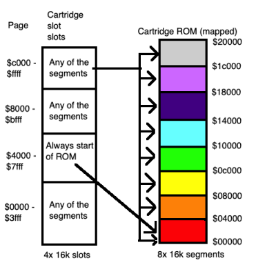
The MSX is based around the Z80, which has a 16-bit address bus, restricting it to 64K of ROM or RAM. The MSX has two cartridge slots, an ‘internal’ slot for the BIOS and RAM and a fourth for ‘misc’ use. Each of these is mapped internally into the physical address space. The cartridge slots have 64K of addressable space mapped into the Z80 physical space.
If this was not complicated enough, many MSX games and applications exceeded this restriction and added a layer of mapping inside the cartridge using bank switching. A register in the cartridge could change the upper bits of the address allowing ROMs larger than 64K.


 compare to each other. Rotations around the vertical axis are also determined in this manner.


