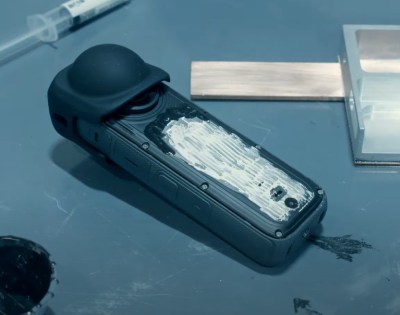
Battlelines are being drawn in Canada over the lowly Flipper Zero, a device seen by some as an existential threat to motor vehicle owners across the Great White North. The story started a month or so ago, when someone in the government floated the idea of banning devices that could be “used to steal vehicles by copying the wireless signals for remote keyless entry.” The Flipper Zero was singled out as an example of such a nefarious device, even though relatively few vehicles on the road today can be boosted using the simple replay attack that a Flipper is capable of, and the ones that are vulnerable to this attack aren’t all that desirable — apologies to the 1993 Camry, of course. With that threat hanging in the air, the folks over at Flipper Devices started a Change.org petition to educate people about the misperceptions surrounding the Flipper Zero’s capabilities, and to urge the Canadian government to reconsider their position on devices intended to explore the RF spectrum. That last bit is important, since transmit-capable SDR devices like the HackRF could fall afoul of a broad interpretation of the proposed ban; heck, even a receive-only SDR dongle might be construed as a restricted device. We’re generally not much for petitions, but this case might represent an exception. “First they came for the Flipper Zero, but I did nothing because I don’t have a Flipper Zero…”
Author: Dan Maloney3211 Articles
How Much Bandwidth Does CW Really Occupy?
Amateur radio license exams typically have a question about the bandwidths taken up by various modulation types. The concept behind the question is pretty obvious — as guardians of the spectrum, operators really should know how much space each emission type occupies. As a result, the budding ham is left knowing that continuous wave (CW) signals take up a mere 150 Hertz of precious bandwidth.
But is that really the case? And what does the bandwidth of a CW signal even mean, anyway? To understand that, we turn to [Alan (W2AEW)] and his in-depth look at CW bandwidth. But first, one needs to see that CW signals are a bit special. To send Morse code, the transmitter is not generating a tone for the dits and dahs and modulating a carrier wave, rather, the “naked” carrier is just being turned on and off by the operator using the transmitter’s keyer. The audio tone you hear results from mixing the carrier wave with the output of a separate oscillator in the receiver to create a beat frequency in the audio range.
That seems to suggest that CW signals occupy zero bandwidth since no information is modulated onto the carrier. But as [Alan] explains, the action of keying the transmitter imposes a low-frequency square wave on the carrier, so the occupied bandwidth of the signal depends on how fast the operator is sending, as well as the RF rise and fall time. His demonstration starts with a signal generator modulating a 14 MHz RF signal with a simple square wave at a 50% duty cycle. By controlling the keying frequency, he mimics different code speeds from 15 to 40 words per minute, and his fancy scope measures the occupied bandwidth at each speed. He’s also able to change the rise and fall time of the square wave, which turns out to have a huge effect on bandwidth; the faster the rise-fall, the larger the bandwidth.
It’s a surprising result given the stock “150 Hertz” answer on the license exam; in fact, none of the scenarios [Allen] tested came close to that canonical figure. It’s another great example of the subtle but important details of radio that [Alan] specializes in explaining.
Continue reading “How Much Bandwidth Does CW Really Occupy?”
Electrospinning Artificial Heart Valves
When you think about additive manufacturing, thoughts naturally turn to that hot-glue squirting CNC machine sitting on your bench and squeezing whatever plastic doodad you need. But 3D printing isn’t the only way to build polymer structures, as [Riley] shows us with this fascinating attempt to create electrospun heart valves.
Now, you may never have heard of electrospinning, but we’ll venture a guess that as soon as you see what it entails, you’ll have a “Why didn’t I think of that?” moment. As [Riley] explains, electrospinning uses an electric field to build structures from fine threads of liquid polymer solution — he uses polycaprolactone (PCL), a biodegradable polyester we’ve seen used in other medical applications, which he dissolves in acetone. He loads it into a syringe, attaches the positive terminal of a high-voltage power supply to the hypodermic needle, and the negative terminal to a sheet of aluminum foil. The charge turns the PCL droplets into fine threads that accumulate on the foil; once the solvent flashes off, what’s left is a gossamer layer of non-woven plastic fabric.
To explore the uses of this material, [Riley] chose to make an artificial heart valve. This required a 3D-printed framework with three prongs, painted with conductive paint. He tried a few variations on the design before settling on a two-piece armature affixed to a rotating shaft. The PCL accumulates on the form, creating a one-piece structure that can be gingerly slipped off thanks to a little silicon grease used as a release agent.
The results are pretty impressive. The structure bears a strong resemblance to an artificial tricuspid heart valve, with three delicate leaves suspended between the upright prongs. It’s just a proof of concept, of course, but it’s a great demonstration of the potential of electrospinning, as well as an eye-opening look at what else additive manufacturing has to offer.
Hackaday Podcast Episode 264: Cheap Minimills, 65-in-1 Electronics, And Time On Moon
It was Dan’s turn behind the mic with Elliot this time as we uncovered the latest from the world of hacking, and what an eclectic mix it was. It was slightly heavy on machining, with a look at mini-mills that are better than nothing, and a DIY DRO that’s A-OK. We also kicked the nostalgia bucket over — whatever that means — and got a new twist on the old “65-in-1” concept, found hidden code in 80s music, and looked at color TV in the US and how it got that way. We’ve got ample alliteration about grep, thoughts about telling time on the Moon, and what does Canada have against the poor Flipper Zero, anyway?
Grab a copy for yourself if you want to listen offline.
Automation Makes Traditional Japanese Wood Finishing Easier
Unless you move in architectural circles, you might never have heard of Yakisugi. But as a fence builder, [Lucas] over at Cranktown City sure has, with high-end clients requesting the traditional Japanese wood-finishing method, which requires the outer surface of the wood to be lightly charred. It’s a fantastic look, but it’s a pain to do manually. So, why not automate it?
Now, before we get into a whole thing here, [Lucas] himself notes that what he’s doing isn’t strictly Yakisugi. That would require the use of cypress wood, and charring only one side, neither of which would work for his fence clients. Rather, he’s using regular dimensional lumber which is probably Douglas fir. But the look he’s going for is close enough to traditional Yakisugi that the difference is academic.
To automate the process of burning the wood and subsequently brushing off the loose char, [Lucas] designed a double-barreled propane burner and placed it inside a roughly elliptical chamber big enough to pass a 2×8 — sorry, metric fans; we have no idea how you do dimensional lumber. The board rides through the chamber on a DIY conveyor track, with flame swirling around both sides of the board for an even char. After that, a pair of counter-rotating brushes abrade off the top layer of char, revealing a beautiful, dark finish with swirls of dark grain on a lighter background.
[Lucas] doesn’t mention how much wood he’s able to process with this setup, but it seems a lot easier than the manual equivalent, and likely yields better results. Either way, the results are fantastic, and we suspect once people see his work he’ll be getting more than enough jobs to justify the investment.
Continue reading “Automation Makes Traditional Japanese Wood Finishing Easier”
A 65-in-1 The 2024 Way
If necessity is the mother of invention, nostalgia must be its stepmother, or its aunt at the very least. The desire to recreate long-obsolete devices simply because they existed while we were growing up is a curious trait, but one that’s powerful enough to drive entire categories of hardware hacking — looking at you, retrocomputing buffs.
Hardware nostalgia isn’t all about 6502s and Z80s, though. Even more basic were the electronic toys of the 1970s, such as the Radio Shack 65-in-1 kit that [Tom Thoen] is currently recreating. The 65-in-1 was a breadboarding kit aimed at the budding electrical engineer, with components mounted to colorful cardboard by spring terminals. The included “lab manual” had circuits that could be quickly assembled using a handful of jumper wires. It was an endlessly fascinating toy that undoubtedly launched many careers, present company included.
While the passage of time may not have dulled [Tom]’s memories of his original 65-in-1, technology has marched on, meaning that certain allowances had to be made to create a modern version. He wisely eschews the cardboard for PCBs, one for each of the major component blocks provided in the original, and uses female header connectors in place of the springs. Component choice is tailored for the times; gone are the ferrite rod antenna and variable capacitor of the original, as well as the incandescent lamp, which is replaced by an LED that would have been a significant fraction of the kit’s $21.95 price back in 1976. There’s no BOM yet, so we can’t say for sure if any of the transistors are germanium, but it’s clear that there aren’t any of the old TO-1 cans. But dismay not, originalists, for the meter, relay, CdS photocell, and “solar battery” all made the final cut.
[Tom] has done some beautiful work here, with more to come. We imagine that 3D printing could be used to recreate some details like the original Morse key and speaker grille. We love the laser-engraved backing board, too, as it captures some of the charm of the original’s wooden box. This isn’t the only love for the “Science Fair” brand we’ve seen lately, either; the nostalgia seems to be contagious.
Hackaday Links: March 24, 2024
Way to rub it in, guys. As it turns out, due to family and work obligations we won’t be able to see the next Great American Eclipse, at least not from anywhere near the path of totality, when it sweeps from Mexico into Canada on April 8. And that’s too bad, because compared to the eclipse back in 2017, “Eclipse 2: Solar Boogaloo” is occurring during a much more active phase in the solar cycle, with the potential for some pretty exciting viewing. The sun regularly belches out gigatons of plasma during coronal mass ejections (CMEs), most of which we can’t see with the naked eye because not only is staring at the sun not a great idea, but most of that activity occurs across the disk of the sun, obscuring the view in the background light. But during the eclipse, we — oops, you — might just get lucky enough to have a solar prominence erupt along the limb of the sun that will be visible during totality. The sun has been quite active lately, as reflected by the relatively high sunspot number, so even though it’s an outside chance, it’s certainly more likely than it was in 2017. Good luck out there. Continue reading “Hackaday Links: March 24, 2024”