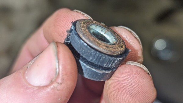
Power Tool Packs Make A Portable Powerhouse

The revolution in portable and cordless appliances has meant that we now own far fewer mains-powered gadgets than we might once have done, but it hasn’t entirely banished the old AC outlet from our lives. Particularly when away from a mains supply it can be especially annoying, but now instead of a generator there’s the option of an inverter. [Thijs Koppen] has made a very neat all-in-one mains power station in a plastic flight case using the ubiquitous and handy standardized Makita power tool packs.

From one perspective this is a simple enough build, because wiring a battery to an inverter isn’t the most difficult of tasks. But he’s designed his own 3D printed Makita battery receptacles which should be of interest to plenty of readers, and with three packs in series he’s sourced an unusual 72 volt inverter to supply mains. The photo of him charging a Tesla with the result is probably more for show than practicality though.

We’ve featured quite a lot of cordless tool battery hacks over the years as their ready availability and quick interchangeability is attractive. If you ever fancy engineering your own mounting, we’ve taken a look at someone doing just that.

A Straightforward AI Voice Assistant, On A Pi

With AI being all the rage at the moment it’s been somewhat annoying that using a large language model (LLM) without significant amounts of computing power meant surrendering to an online service run by a large company. But as happens with every technological innovation the state of the art has moved on, now to such an extent that a computer as small as a Raspberry Pi can join the fun. [Nick Bild] has one running on a Pi 4, and he’s gone further than just a chatbot by making into a voice assistant.

The brains of the operation is a Tinyllama LLM, packaged as a llamafile, which is to say an executable that provides about as easy a one-step access to a local LLM as it’s currently possible to get. The whisper voice recognition sytem provides a text transcript of the input prompt, while the eSpeak speech synthesizer creates a voice output for the result. There’s a brief demo video we’ve placed below the break, which shows it working, albeit slowly.

Perhaps the most important part of this project is that it’s easy to install and he’s provided full instructions in a GitHub repository. We know that the quality and speed of these models on commodity single board computers will only increase with time, so we’d rate this as an important step towards really good and cheap local LLMs. It may however be a while before it can help you make breakfast.

Continue reading “A Straightforward AI Voice Assistant, On A Pi”

Double Fed Induction Motors: Clever Motor Control Through Frequency

Somewhere in most engineering educations, there’s a class on induction motors. Students learn about shaded-pole motors, two-phase and three-phase motors, squirrel cage motors, and DC-excited motors. It’s a pre-requisite for then learning about motor controllers and so-called brushless DC motors. [Jim Pytel] takes this a step further in a series of videos, in which he introduces the doubly fed induction motor. If a conventional three-phase motor can have its coils in either rotor or stator, here’s a motor with both. The special tricks with this motor come in feeding both rotor and stator with separate frequencies, at which point their interactions have useful effects on the motor speed.

There are two videos, both of which we’ve put below the break. Understanding the complex interaction of the two sets of magnetic fields is enough to make anyone’s brain hurt, but the interesting part for us is that the motor can run faster than either of the two drive frequencies.

Sadly we’re not aware of any easily available motors using this configuration, so we don’t think it will be possible to easily experiment. But if you want to amaze your friends with an in-depth knowledge of motors, take a look at the videos below.

Continue reading “Double Fed Induction Motors: Clever Motor Control Through Frequency”

3D Print Train Wheels For Garden Railway

There’s something magical about a train, whether you call it a railway or a railroad, plenty of us have hankered after our own little piece of line on which to shunt wagons or chuff around our domain. Envy [Otis Rowell] then, because he’s made himself a garden railway with the laudable purpose of moving wood pellets for his heating. A mere garden railway may be cool but it’s not in itself special, so the reason we’re featuring it here comes from something else. He’s making his rail wheels by 3D printing them with a normal printer.

It’s important to understand that these wheels are not for a high-speed mainline express freight train but for a small flat car designed to carry a modest tub of pellets, thus they are less in need of high strength than their full-size cousins. But even a small car on garden railway-sized aluminum rails can exert significant force, so we would be fascinated to see how well these do. The write-up is a work in progress as this article is being written so we know there’s more to come, but there’s no harm in speculating as to how a better 3D-printed wheel might be made. We would be particularly curious for example as to whether a novel slicing regime could be used to make a stronger wheel.

If backyard railways interest you, it’s not the first time we’ve seen one.

A 1960s PLC Gives Up Its Secrets

When it comes to process automation, the go-to part in most industrial settings is a Programmable Logic Controller, or PLC. These specialized computers will have a modern microcontroller running the show, but surprisingly the way they are programmed still has echoes of a time before electronic PLCs when such control would have been electromechanical.

[Thomas Scherrer] has an interesting design to tear down, it’s a Siemens electromechanical motor controller from the early 1960s. It’s not quite the huge banks of relays which would have made a fully-blown PLC back in those times, but it’s a half-way house with some simple programming capability in the form of several channels of adjustable time delay.

We’re partly sad to see this unit being subjected to a destructive teardown, but nevertheless it’s interesting to see all those very period components. The current sensor has a mechanism similar to a moving coil meter, and the four-channel timer is a mechanical sequencer with four adjustable cam-driven switches. We’re not sure we would be cracking open selenium rectifiers with such nonchalance though.

These units were built to a very high quality indeed, and though it’s obvious this one comes from a decommissioned installation it’s not beyond possibility to think there might be some of them still doing their job over six decades after manufacture. Have any of you seen one of these or something like it in operation recently? Let us know in the comments. Meanwhile the video is below the break.

Continue reading “A 1960s PLC Gives Up Its Secrets”

Lift Those Pins With Ease

Reworking is one of the regular tasks of anyone who is involved in an electronic design process, because try as we might, it’s rare to get a design perfectly right the first time. Some reworking tasks are more difficult than others though, and we have to admit that lifting an IC pin doesn’t always result in success. But with this video from [Mr. SolderFix] there’s hope for conquering the technique, as he takes us through the best pin-raising technique on a variety of packages.

The trick it seems is to lift the pin first without attempting to disengage it from the molten solder, then returning to it with some copper braid to remove the solder and leave it raised. Once the secret is revealed it’s so easy, something a Hackaday scribe should be able to do. He does sound a note of caution though, as some packages are prone to disintegrating when stressed. A broken SOT-23 is not something anyone likes to see through their magnifier.

His channel is full of such no-nonsense soldering advice, and should be a fascinating browse for many readers. Meanwhile we’ve covered quite a bit of rework technique ourselves, such as last year when we looked at BGA work.

Continue reading “Lift Those Pins With Ease”

Parts We Miss: The Mains Transformer

About two decades ago there was a quiet revolution in electronics which went unnoticed by many, but which overturned a hundred years of accepted practice. You’d have noticed it if you had a mobile phone, the charger for your Nokia dumbphone around the year 2000 would have been a weighty device, while the one for your feature phone five years later would have been about the same size but relatively light as a feather. The electronics industry abandoned the mains transformer from their wall wart power supplies and other places in favour of the much lighter and efficient switch mode power supply. Small mains transformers which had been ubiquitous in electronics projects for many years, slowly followed suit.

Coils Of Wire, Doing Magic With Electrons

Inside and outside views of Jenny Lists's home made linear power supply from about 1990
This was a state of the art project for a future Hackaday scribe back in 1990.

A transformer works through transferring alternating electrical current into magnetic flux by means of a coil of wire, and then converting the flux back to electric current in a second coil. The flux is channeled through a ferromagnetic transformer core made of iron in the case of a mains transformer, and the ratio of input voltage to output voltage is the same as the turns ratio between the two. They provide a safe isolation between their two sides, and in the case of a mains transformer they often have a voltage regulating function as their core material is selected to saturate should the input voltage become too high. The efficiency of a transformer depends on a range of factors including its core material and the frequency of operation, with transformer size decreasing with frequency as efficiency increases.

When energy efficiency rules were introduced over recent decades they would signal the demise of the mains transformer, as the greater efficiency of a switch-mode supply became the easiest way to achieve the energy savings. In a sense the mains transformer never went away, as it morphed into the small ferrite-cored part running at a higher frequency in the switch-mode circuitry, but it’s fair to say that the iron-cored transformers of old are now a rare sight. Does this matter? It’s time to unpack some of the issues surrounding a small power supply. Continue reading “Parts We Miss: The Mains Transformer”