
Fidget toys are everywhere these days. A particularly popular type simply puts some keyboard switches on a plate to provide a certain type of clicky satisfaction. [wjddnjsdnd] took that concept a step further, building a keychain-sized fidget toy that actually has games on it.
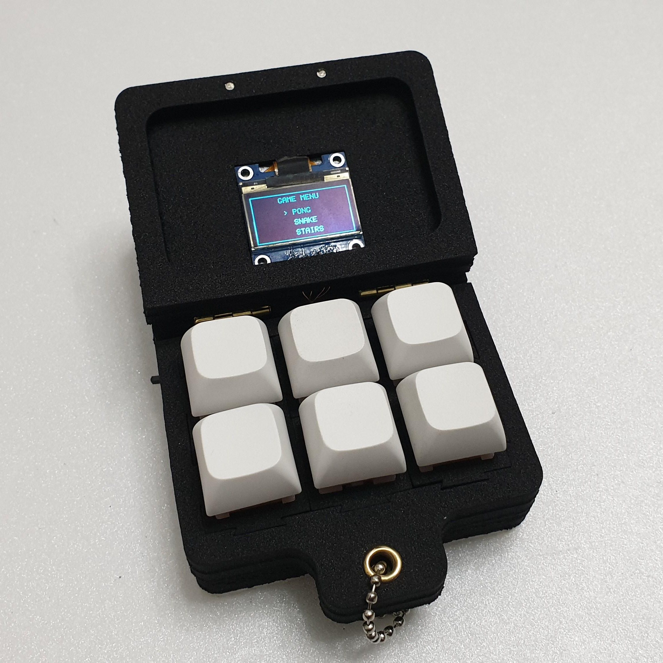 The build is based around six key switches in a 2 x 3 array. The key switches are notable in this case for being magnetic shaft keys. Rather than using a mechanical switch to indicate a keypress, the keycap instead merely moves a magnet which triggers a signal in a hall effect sensor beneath the key. In this case, the build uses A3144 hall effect sensors, which are read by the Arduino Nano running the show. The Nano is also hooked up to a small SSD1306 OLED display over I2c, which it uses for displaying the game state. There’s also a TP4056 module to handle charging the attached 380 mAh lithium-ion battery which powers the pocket-sized device.
The Arduino Nano is not a powerful platform for gaming, but it can handle the basics. The Gamebox Clicker, as it’s called, features a Pong clone, a stairs game, and a recreation of Snake. Think early mobile phone games, and you’d be on the money.
It’s an interesting build, and one that would be a great way to get used to using magnetic key switches as well as small embedded displays. We’ve seen Arduino boards turned into microconsoles many times before, too. If you’d like to sound off about magnetic vs. mechanical key switches, jump into the comments, or otherwise let us know about your best electronic fidget projects on the tipsline. Happy hacking.


