Intro To DC Motor Control Using The SN754410

So your electronic hobby skills are coming along quite nicely but you’re not very comfortable doing more than blinking a few LEDs. Now’s a good time to try something new by driving a couple of DC motors.

You probably know that you can’t just hook these up to the pins of your favorite uC and call it good. The motors draw a lot of current (especially if they’re strained in lifting a heavy load) which would burn out your logic circuitry. Add to this the excess induced current that is generated when a spinning motor is shut off and you’re going to need a control system that can handle these dangers.

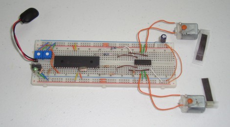
Enter the h-bridge motor driver. [Chris] has guided us through the process of building and using a H-bridge in the past. This time he’s using a motor controller that has four half H-bridges built into it. He hooks up the SN754410 to two motors, giving him speed and direction control for both based on the duty cycle of a PWM signal entering the chip for less than $2.50. Check out the video after the break for an overview of his methodology, then work your way through the multi-page post that he recently published.

Continue reading “Intro To DC Motor Control Using The SN754410”

LG TV Hacking Via Serial Connection Or IR Codes

[Brendan Robert] has been sending us forum thread links outlining the things he’s learned while hacking LG televisions. They were a bit hard to follow for the uninitiated, so we asked if he could give us an overview of what he’s been working on. Not only did he do that, but he made a little Hackaday shout-out seen above by adding the skull and cross-wrenches as one of the menu overlays.

He’s using a TV as his computer monitor, which he picked up at a discount because it was a display model. Without the original remote, and wanting to have features like power-saving mode which is standard on monitors but not on this TV, he decided to see what he could accomplish. A couple of things made this quite a bit easier. First, there’s an RS232 port built into the back which removes the need to investigate and solder your own onto the board. Secondly, since LG built on the Linux kernel for the set, you can download some of the firmware sources from their website.

What he came up with is a script that will find and communicate with the TV over the serial connection. The test script used during development polled every possible command, looking for valid return values. Once [Brendan] established which commands work and what they do, he was able to take command of the unit, writing scripts to adjust brightness based on the ambient light in the room as seen from the computer’s webcam. Make sure you check out the sub-pages to his post that detail the brightness adjustments, stand-by functionality, custom overlay graphics, and the extra commands he uncovered.

Output Up To 768 PWM Signals From One Arduino

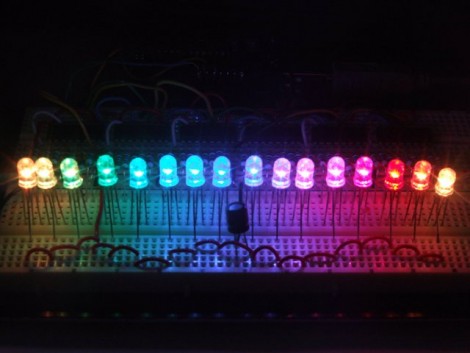
Here’s an Arduino library that will let you drive a very large number of LEDs. [Elco Jacobs], an electrical engineering student, is the author of the library. He has a work-study job that has him helping out others with their electrical projects and he was constantly being solicited for methods to control droves of light emitting diodes. This was the motivation that led him to produce the dazzling 16 RGB LED example seen in the video after the break.

His setup doesn’t use expensive LED drivers, but instead utilizes 595 shift registers which are both common and cheap. He calculates that it is possible to control up to 96 of these shift registers, each driving 8 LEDs, with reasonably satisfying results. This is thanks to his well-optimized code that manages to drive the clock pin of the registers at 1.33 MHz. This optimization is done by writing each command in assembly, which allows him to precisely count the cycles. Each individual pin takes 12-13 cycles to address, totally 9984 cycles at worst when addressing the maximum number of outputs.

[Elco] thinks this is as fast as he can make the routine run, but he is asking for help with testing. If you think you know how to squeeze out a few more cycles, make sure you join in on his forum thread.

Continue reading “Output Up To 768 PWM Signals From One Arduino”

Obstacle Avoiding Hexapod From Reused Parts


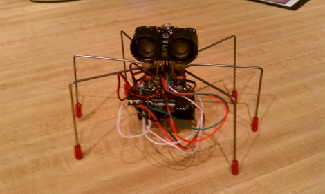
[Rob] built this hexapod one day when he had some free time after work. Just like the last hexapod we saw, he based the build on the Pololu design which uses three servo motors for surprisingly reliable movement.

The hardware is very straight forward. A Dorkboard serves as the brain. It’s a PCB that is wider on each side by the width of one female pin-header than a standard AVR 28-pin microcontroller. This gives easy access to all of the pins on the Arduino chip while making it small and light. You can see that a four-pack of batteries hangs below the servo motors to provide power.

Protruding above the 6-legger is a PING ultrasonic rangefinder. This adds autonomy to the little robot, which you can see running some obstacle avoidance routines in the video after the break. We’ve asked [Rob] if is able to share his code and will update this post if we hear back from him.

Update: Here’s a link to the sketch, and we’ve updated the picture with one that [Rob] sent to us.

Continue reading “Obstacle Avoiding Hexapod From Reused Parts”

One Really Big Quadcopter That Is Following In The Steps Of The Spruce Goose

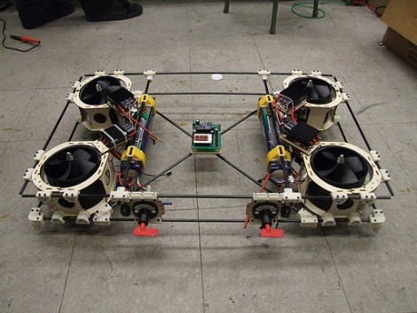
Behold the Land-Bear-Shark, a quadcopter on a rather grand scale. At a full eight kilograms it’s an easy target to compare the [Howard Hughes] behemoth, but in addition to the weight, this still has yet to make its first flight.

To give you some scale to the image above, the board at the center is an Arduino. It controls the beast, along with the help of a SparkFun IMU board which rides atop. Really, if any quadcopter of this size has a chance of working, this should be the one. The construction is beautiful, making use of carbon fiber rod along with 3D-printed connectors to assemble the frame. A lot of thought has gone into small things like conserving weight used on the landing gear, which are incorporated into the bottom corner brackets. The batteries are connected in a manner that makes them easy to adjust, acting as ballast for balancing the craft.

We’re keeping our fingers crossed that this will be more than the tongue-in-cheek title of the post which calls it a Quadrotor-shaped sculpture.

[via Adafruit]

2011 CCC R0ket Badge

[Geekabit] wrote in asking if we’d seen the 2011 CCC badges yet. The answer is NO, we haven’t seen them because the image above is the only sneek peek we can find on their broken-certificate website. But we are glad that he shared the link with us, because it does tell the tale of what hardware and firmware features will be on this year’s badge.

Right off the bat we need to applaud them for several things. Most notably, the 3.7 volt 600 mAh LiPo battery which can be recharged via the USB port. It boasts an ARM Cortex M3 processor which is running what they call and ‘unbrickable’ bootloader that is programmed via the USB port. You can see there is an LCD screen which we’d guess is about 128×128 pixels (correct us if you know otherwise). You’ll be able to interact using a 5-way button, via the RF transceiver, and possibly using an optical interface but we’re not sure that feature made it into the final design. They’ve also rolled in a shield system for extra harware so that you can design your own add-ons before you get there.

As always, if you get your hands on one of these, we want to hear all about your project as well as get an overview of the stock badge and its features so don’t forget to drop us a line.

Update: [Never_gonna] left a comment with a link to a series of posts about r0cket development including a video which we’ve embedded after the break. Thanks!

Continue reading “2011 CCC R0ket Badge”

Modelling Chemical Reactions Using An FPGA

[Bruce Land] is a professor at Cornell University who was looking for a way to quickly solve chemical kinetic systems. He had used MATLAB but longed for a faster method. His upgrade achieves a 100 times speed increase by using an FPGA as a parallel stochastic solver.

It works by generating 100 pseudo-random 16-bit numbers using an Altera DE2 board. This is done once per cycle at 50 MHz so we’re talking about a lot of random numbers. They are run through the solver algorithms and used to compute each reaction cycle. On a 3.8 GHz P4 process running the MATLAB version one of these cycles would take about 1000 seconds, so the speed improvement can immediately be felt. It’s wonderful to have this new tool. It does make us wonder what could be done with GPU processing that we’ve seen for password cracking or bit coin mining. Much like FPGAs a GPU is prefect for running a large number of parallel operations.