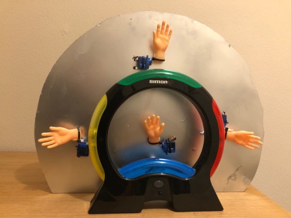
Most modern computer games have a clearly-defined end, but many classics like Pac-man and Duck Hunt can go on indefinitely, limited only by technical constraints such as memory size. One would think that the classic electronic memory game Simon should fall into that category too, but with most humans struggling even to reach level 20 it’s hard to be sure. [Michael Schubart] was determined to find out if there was in fact an end to the latest incarnation of Simon and built a robot to help him in his quest.
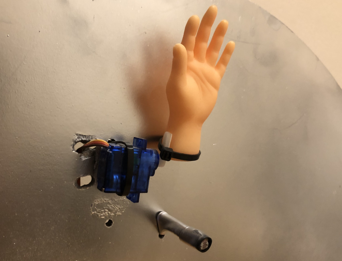
The Simon Air, as the newest version is known, uses motion sensors to detect hand movements, enabling no-touch gameplay. [Michael] therefore made a system with servo-actuated silicone hands that slap the motion sensors. The tone sequence generated by the game is detected by light-dependent resistors that sense which of the segments lights up; a Raspberry Pi keeps track of the sequence and replays it by driving the servos.
We won’t spoil the ending, but [Michael] did find an answer to his question. An earlier version of the game was already examined with the help of an Arduino, although it apparently wasn’t fast enough to drive the game to its limits. If you think Simon can be improved you can always roll your own, whether from scratch or by hacking an existing toy.
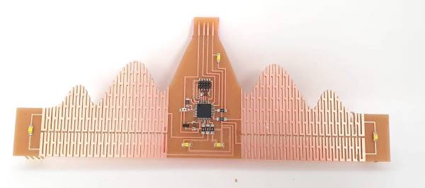
Printed circuit boards can be square, round, octagonal, or whatever shape you desire. But there’s little choice when it comes to the third dimension: most PCBs are flat and rigid. Sure, you can make flexible PCBs like the kapton-backed ones you find inside electronic gadgets, but those are complicated to work with. As it turns out however, you can also make flexible boards using regular PCB material: check out [Rehana Al-Soltane]’s Flexible Crown PCB, a project she did as part of [Neil Gershenfeld]’s “How To Make (Almost) Anything” class at MIT.
The basic idea is to create flexures in the PCB by milling out several long slots with thin pieces connecting the two sides. [Rehana] got this idea from [Quentin Bolsée]’s flexible capacitive sensor project and applied it to make a crown-shaped PCB with sparkly LEDs. The crown can bend through 180 degrees and can actually be worn as a head ornament, with pin headers to clamp it down on the wearer’s hair.
[Rehana] used a tool called svg-pcb to design the board. This is an open source toolkit that lets you design PCBs by describing them in code, rather than drawing shapes by hand. Although this might look a bit odd if you’re used to working with traditional PCB design software, it’s ideal for making repetitive structures like the flexures in the crown: simply write a for loop and let the tool generate a perfect array of identical slots.
Fabricating the Flexible Crown posed a few difficulties of its own, because the PCB began to flex and wiggle itself loose before the milling process was finished. As it turned out, the trick was to cut all the slots on the interior first and only mill the board’s outline as the very last step.
Adding flexures to a PCB like this looks like a promising technique and we’ll keep an eye on further developments in this field. There are other ways of making bendy boards though: researchers at the University of Maryland used a laser engraver to make foldable PCBs. Our 2019 Flexible PCB Contest also yielded several impressive implementations.
Over the years, there have been several memory and display technologies that served a particular niche for a while, only to be replaced and forgotten when a more suitable technology came along. One of those was the dekatron: a combination memory and display tube that saw some use in the 1950s and ’60s but became obsolete soon after. Their retro design and combined memory/display functionality make them excellent components for today’s clock hackers however, as [grobinson6000] demonstrates in his Dekaclock project.
A dekatron tube is basically a neon tube with ten cathodes arranged in a circle. Only one of them is illuminated at any time, and you can make the tube jump to the next cathode by applying pulses to its pins. The Dekaclock uses the 50 Hz mains frequency to generate 20 ms pulses in one tube; when it reaches 100 ms, it triggers the next tube that counts hundreds of ms, which triggers another one that counts seconds, and so on with minutes and hours.
The Dekaclock uses no semiconductors at all: the entire system is built from glass tubes and passive components. However, [grobinson6000] also built an auxiliary system, full of semiconductors, that makes the clock a bit easier to use. It sits on top of the Dekaclock and automatically sets the correct time using a GPS receiver. It also keeps track of the time displayed by the dekatrons, and tells you how far they have drifted from their initial setting.
Both systems are housed in sleek wooden cases that perfectly fit the tubes’ retro aesthetic. [grobinson6000] was inspired to make the Dekaclock after watching another dekatron clock we featured earlier, and designed the GPS receiver to work alongside it. Dekatrons are surprisingly versatile devices: you can use them to make anything from internet speed gauges to kitchen timers.
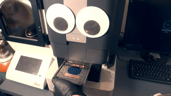
Over the past few years we’ve seen several impressive projects where people try to manufacture integrated circuits using hobbyist tools. One of the most complex parts of this process is lithography: the step in which shapes are drawn onto a silicon wafer. There are several ways to do this, all of them rather complicated, but [Zachary Tong] over at Breaking Taps has managed to make one of them work quite well. He shares the results of his electron-beam lithography experiments in his latest video (embedded below).
In e-beam lithography, or EBL, shapes are drawn onto a wafer using an electron beam in a vacuum chamber. This is a slow process compared to optical lithography, as used in mass production, but it is reasonably simple and very flexible. [Zach] decided to use his electron microscope as an e-beam litho machine; although not designed for lithography, it has the same basic components as a real EBL machine and can act as a substitute with a bit of software tweaking.
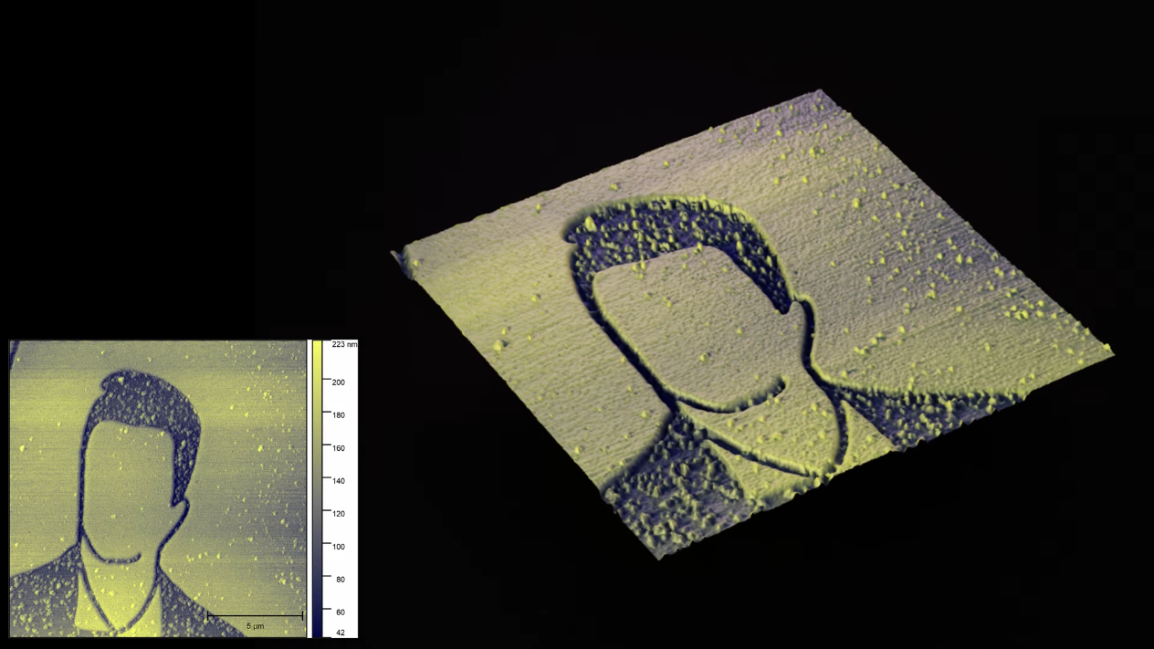
[Zach] also has an atomic force microscope, which he used to make these beautiful images.The first step is to coat a wafer with a layer of e-beam resist. [Zach] used PMMA, commonly known as acrylic plastic, and applied it using spin coating after dissolving it in anisole. He then placed the wafer into the electron microscope and used it to scan an image. The image was then developed by rinsing the wafer in cold isopropyl alcohol.
[Zach] explains the whole process in detail in his video, including how he tuned all the parameters like resist thickness, beam strength, exposure time and development time, as well as the software tricks needed to persuade the microscope to function as a litho machine. In his best runs he managed to draw lines with a width of about 100 nanometers, which is seriously impressive for such a relatively simple setup.
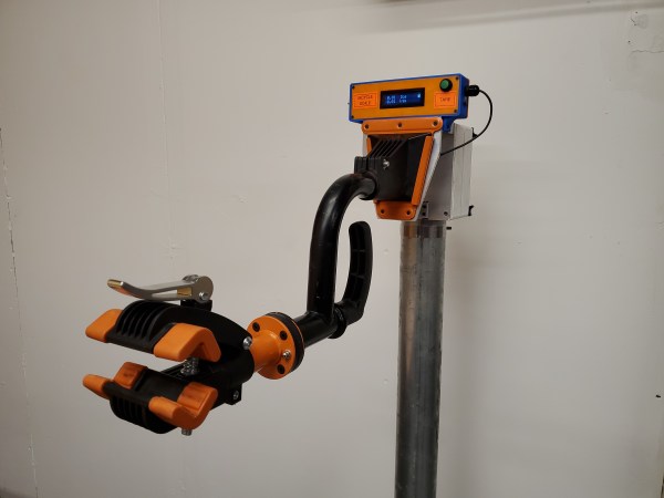
If you’ve ever done maintenance or repair work on your bicycle, you’ll know that positioning a bike in your workshop isn’t trivial. You can use your bike’s kickstand, or lean it against a wall, but then you can’t work on the wheels. You can place it upside-down, but then the shifters and brake levers are hard to reach. You can hang it from the ceiling, but then you first need to install hooks and cables in hard-to-reach places. Ideally you’d want to have one of those standing clamp systems that the pros use, but their price is typically beyond a hobbyist’s budget.
Or at least, that’s how it used to be. As [Dane Kouttron] discovered, a simple wall-mounted bike clamp can be had for as little as $35 on eBay, and can easily be converted into a smart mobile repair stand. [Dane] fashioned an adjustable stand from some steel pipes he had lying around, and 3D-printed an adapter bracket to mount the bike clamp on it. This worked fine, but why stop at a simple clamp when you can expand it with, say, an integrated scale to weigh your bikes while you work on them? Continue reading “DIY Repair Stand Holds Your Bike And Weighs It”→
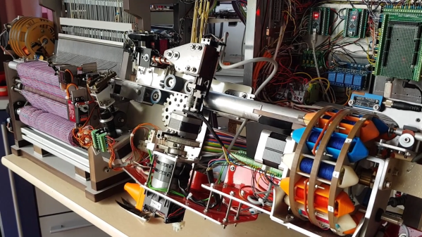
Weaving is one of the oldest crafts in the world, and was also among the first to be automated: the Industrial Revolution was in large part driven by developments in loom technology. [Roger de Meester] decided to recreate that part of the industry’s history, in a way, by building his own desktop-sized, fully automatic loom. After a long career in the textiles industry he’s quite the expert when it comes to weaving, and as you’ll see he’s also an expert machine builder.
[Roger]’s loom is of a specific type called a dobby loom, which means that the vertical threads (the warp) can be moved up and down in various ways to create different patterns in the fabric. The horizontal wires (the weft) are created by a shuttle moving left and right, carrying a bobbin that unspools as it travels. A comb-shaped plate (the reed) then fixes the fresh weft in its place. [Roger]’s videos (embedded below) clearly show this mechanism in action, as well as the loom’s overall design.
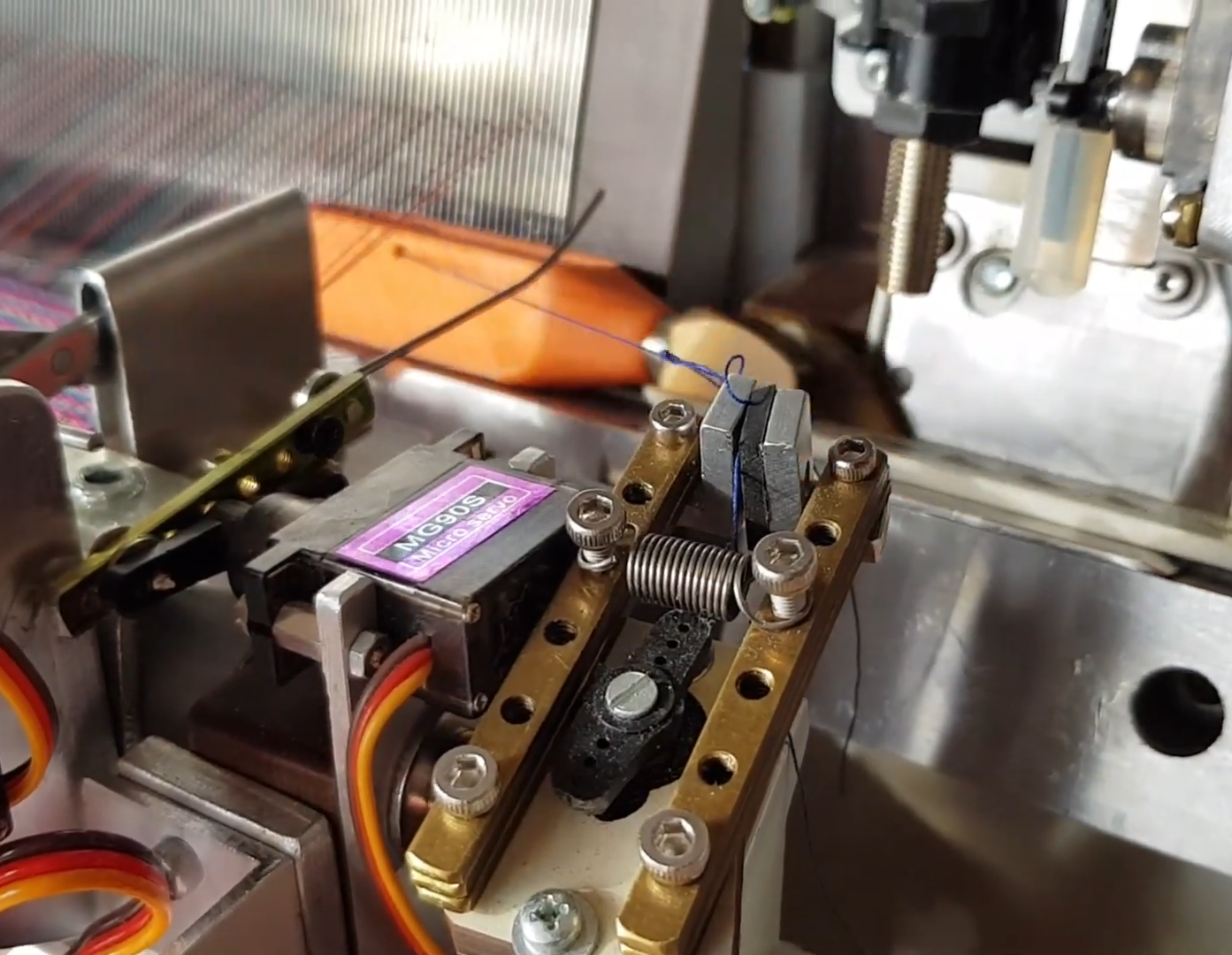
A clamp hold the end of the weft as the shuttle starts its run
The 3D printed shuttle is moved back and forth through the warp by a belt-driven system that grabs the magnetic end of the shuttle. Revolving storage drums on either side of the machine enable the use of different thread colors for each shuttle run. Shuttles are exchanged by a robotic arm that picks them up and places them onto the track; there’s a clamp that grabs the end of the thread as the shuttle starts its run, and a wire cutter to detach it when the shuttle is up for replacement.
This intricate mechanical dance is controlled by a set of Arduino Megas and Nanos. They drive all the servos, DC motors, and steppers while reading out an array of sensors and switches. The system can even detect several faults: the weft is checked for proper tension after each cycle, shuttles with empty bobbins are automatically discarded, while a laser keeps an eye on the warp to ensure none of the threads have snapped.
The entire machine is of [Roger]’s own design; apart from 3D-printed and CNC-machined parts, he also re-used components from various pieces of discarded machinery. His ultimate purpose is to use this machine to make specialized fabrics for medical or industrial use: for example, it can use conductive threads to make fabrics with built-in sensors.
Although this isn’t the first DIY automatic loom we’ve featured, it’s definitely the most advanced. Previous examples, like this 3D-printed miniature version or this neat computer-controlled one can’t really compare to [Roger]’s 26 cm reed width and wide customizability. If you prefer to keep things a bit simpler, you can also use a 3D-printer to directly print certain fabrics.
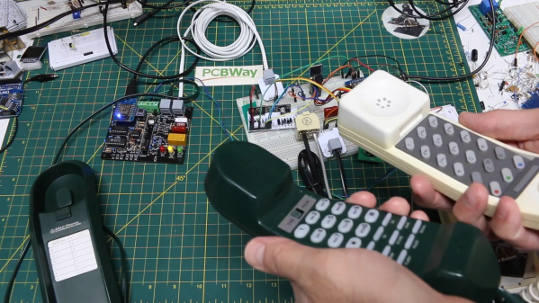
Analog phones may be nearly obsolete today, but having served humanity for well over a century they’re quite likely to pop up in drawers or attics now and then. If you’ve got a few of them lying around and you think it’d be cool to hook them up and make your own local telephone system, check out [Gadget Reboot]’s latest work. His video series shows all the steps towards making a fully-functional wired phone system.
Of course, dedicated phone exchanges for home or small business use are not hard to find, but [Gadget Reboot] decided it would be way more interesting to design his own system from the ground up. To begin with, he used off-the-shelf subscriber line interface circuits (SLICs) to implement the correct voltages, currents and impedances to drive analog phones. He then added a DTMF decoder chip to allow the phone to dial a number, and hooked up both systems to an ESP8266 which controls the entire system. It implements the different states of picking up, dialing, ringing and hanging up, and also generates the corresponding audio signals.
The system becomes even more interesting through the implementation of a multi-exchange layout, just like in large-scale phone systems: when a number is dialled that’s connected to a different exchange, then a connection must be made between two exchanges in order to complete the call. Large-scale systems use dedicated protocols like SS7, but [Gadget Reboot] preferred to keep things simple and used an RS-485 connection. The two ESPs check each others status and if everything’s in order, a relay connects the two lines and the circuit is completed.
The current system is a bit of a mess of wires, but it works, and [Gadget Reboot] plans to make a cleaner setup based on custom circuit boards, possibly expanding it with functions like modem support. In any case it’s already way more advanced than a simple electromechanical system. Want to know more about classic phone networks? We’ve got you covered.
 The Simon Air, as the newest version is known, uses motion sensors to detect hand movements, enabling no-touch gameplay. [Michael] therefore made a system with servo-actuated silicone hands that slap the motion sensors. The tone sequence generated by the game is detected by light-dependent resistors that sense which of the segments lights up; a Raspberry Pi keeps track of the sequence and replays it by driving the servos.