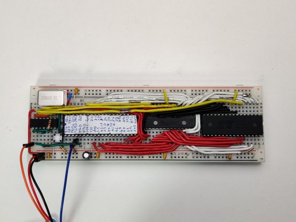
A breadboard with a few DIP chips

Minimalist 6502 System Uses A CPU And Not Much Else

A central processing unit, or CPU, is the heart of any computer system. But it’s definitely not the only part: you also need RAM, ROM and at least some peripherals to turn it into a complete system that can actually do something useful. Modern microcontrollers typically have some or all of these functions integrated into a single chip, but classic CPUs don’t: they were meant to be placed on motherboards along with dozens of other chips. That’s why [c0pperdragon]’s latest project, the SingleBreadboardComputer, is such an amazing design: assisting its 6502 CPU are just four companion chips.

The entire system takes up just one strip of solderless breadboard. Next to the CPU we find 32 KB of SRAM, 32 KB of flash and a clock oscillator. The fifth chip is a 74HC00 quad two-input NAND gate, which is used as a very tiny piece of glue logic to connect everything together. Two of its NAND gates are used for address decoding logic, allowing either the ROM or RAM chip to be selected depending on the state of the CPU’s A15 line as well as blocking the RAM during the low phase of the system clock. The latter function is needed because the address lines are not guaranteed to be stable during the low phase and could cause writes to random memory locations.

The remaining two NAND gates are connected as an RS-flipflop in order to implement a serial output. This is needed because the CPU cannot keep its outputs in the same state for multiple clock cycles, which is required for a serial port. Instead, [c0pperdragon] uses the MLB pin, normally used to implement multiprocessor systems, to generate two-clock pulses, and stores the state in the flipflop for as long as needed. A few well-timed software routines can then be used to transmit and receive serial data without any further hardware.

Currently, the only software for this system is a simple demonstration that sends back data received on its serial port, but if you fancy a challenge you could write programs to do pretty much anything. You could probably find some inspiration in other minimalist 6502 boards, or projects that emulate a complete motherboard in an FPGA.

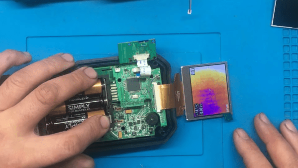
A working, partially disassembled thermal camera

Cheap Display Fix Brings Thermal Camera Back To Life

When it comes to repairability of electronic devices, much depends on how helpful the original manufacturer is. Some make repairs very easy by publishing detailed service manuals and selling spare parts. Others keep everything under wraps to protect their intellectual property, turning even a supposedly simple fix into a reverse engineering ordeal. When [BuyItFixIt] got his hands on a FLIR multimeter-thermal camera combination instrument with a broken display, he quickly found that FLIR was firmly in the “all our designs are top secret” camp and wouldn’t even tell him what kind of display they had used.

Not to be deterred, [BuyItFixIt] took the meter apart and tried to find out what was going wrong. The signals from the microprocessor seemed to reach the display OK, so the fault was somewhere in the screen itself. The display’s part number didn’t return any useful results online, but AliExpress did have a very similar-looking display available with a slightly different part number. This display seemed to work at first, but the instrument then got caught in a boot loop.

Unlike FLIR, the supplier of the replacement display was happy to supply datasheets, and even had one available for the original FLIR part. With this new information [BuyItFixIt] was able to deduce that the new screen didn’t output one signal that the processor expected to see, causing it to reset itself. A simple workaround was to connect the corresponding pin to a PWM signal from the backlight controller, which fooled the CPU into thinking the proper display was connected.

In this case, a $12 display and a single piece of wire were enough to bring an expensive instrument back to life, but things are not always that simple. More complex machines can take weeks to debug, even if parts are available. If not, you might even need to design your own. Continue reading “Cheap Display Fix Brings Thermal Camera Back To Life”

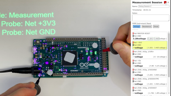
A PCB with several points highlighted by a projection system

Augmented Reality Workbench Helps You To Debug Your Boards

No matter how advanced your design skills, the chances are you’ll need to spend some time chasing bugs in your boards after they come back from the assembly house. Testing and debugging a PCB typically involves a lot of cross-checking between the board, the layout and the schematic, which quickly becomes tiresome even for mildly complex designs. To make this task a bit easier, [Ishan Chatterjee] and colleagues at the University of Washington have designed the Augmented Reality Debugging Workbench, or ARDW for short.

The ARDW is a setup consisting of a lab workbench with an antistatic mat, a selection of measurement instruments and a PC. You can simply place your board on the bench, open the schematic and layout in KiCAD and start measuring and debugging your design as you normally would, but the real magic happens when you select a new icon in KiCAD that exports the schematic and layout to the ARDW system. From that moment, you can select components in your schematic and have them highlighted not only on the layout, but on the physical board in front of you as well. This is perhaps best demonstrated visually, as the team members do in the video embedded below.

The real-life highlighting of components is achieved thanks to a set of cameras that track the motion of everything on the desk as well as a video projector that overlays information on top of the PCB. All of this enables a variety of useful debugging features: for example, there’s an option to highlight pin one on all components, enabling a simple visual check of each component’s orientation. You can select all Do Not Populate (DNP) instances and immediately see if all highlighted pads are empty. If you’re not sure which component you’re looking at, just point at it with your multimeter probe and it’s highlighted on the schematic and layout. You can even place your probes on a net and automatically log the voltage for future reference, thanks to a digital link between the multimeter and the ARDW software.

In addition to designing and building the ARDW, the team also performed a usability study using a group of human test subjects. They especially liked the ability to quickly locate components on crowded boards, but found the on-line measurement system a bit cumbersome due to its limited positional accuracy. Future work will therefore focus on improving the resolution of the projected image and generally making the system more compact and robust. All software is freely available on the project’s GitHub page, and while the current system looks a little complex for hobbyist use, we can already imagine it being a useful tool in production environments.

It’s not even the first time augmented reality has been used for PCB debugging: we saw a somewhat similar system at the 2019 Hackaday Superconference. AR can also come in handy during the design and prototyping phase, as demonstrated by this AR breadboard.

Continue reading “Augmented Reality Workbench Helps You To Debug Your Boards”

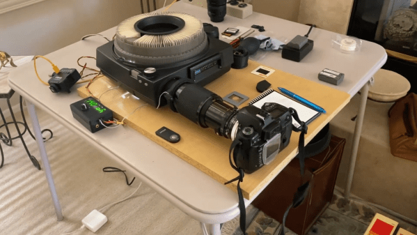
A slide carousel with a DSLR attached to its lens output

Digitize Your Slide Deck With This Arduino-Powered Slide Carousel

If you’re above a certain age, you probably remember the atmosphere of a pre-Powerpoint 35 mm slide show. The wobbly screen being unrolled, the darkened room, the soft hum of the projector’s fan, the slightly grainy picture on the screen and that unmistakable click-whoosh-clack sound as the projector loaded the next slide. Nowadays you’ll be hard pressed to find anyone willing to set up a screen and darken the room just to watch a few photos, so if you still have any slides lying around you’ll probably want to digitize them. If you’ve also kept your projector then this doesn’t even have to be that difficult, as [Scott Lawrence] shows in his latest project.

[Scott] made a setup to directly connect a DLSR, in this case a Nikon D70, to a Kodak 760 slide carousel. The attachment is made through a 3D-printed adapter that fits onto the Nikon’s macro lens on one side and slides snugly into the carousel’s lens slot on the other. The adapter also holds an IR transmitter which is aimed at the camera’s receiver, in order to trigger its remote shutter release function.

The carousel’s original light source was replaced with a compact LED studio light, which allows for precise brightness control and of course remains nice and cool compared to the original incandescent bulb. The light, camera and carousel motor are all controlled through a central user interface driven by an Arduino Leonardo which can automatically advance the carousel and instruct the camera to take a picture, thereby taking the hard work out of digitizing huge stacks of slides.

[Scott] plans to make the software and STL files available on GitHub soon, so anyone can go ahead and turn their projector into a digitizer. If you’ve misplaced your projector however, a simple 3D-printed slide adapter for your camera also works for small slide decks.

Continue reading “Digitize Your Slide Deck With This Arduino-Powered Slide Carousel”

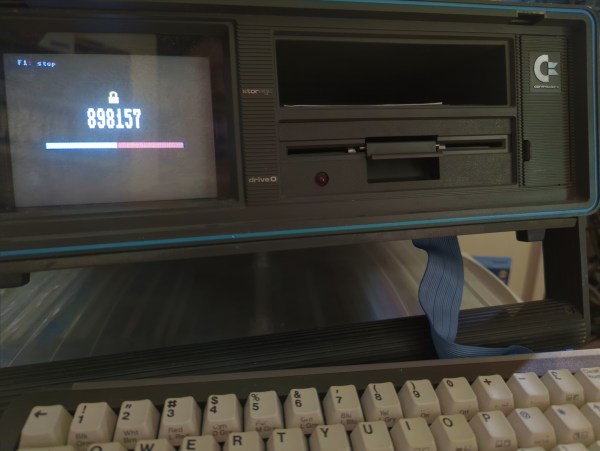
A Commodore SX-64 showing a six-digit code and a countdown timer

Generating Two-Factor Authentication Codes With A Commodore 64

If you’ve used a corporate VPN or an online-banking system in the past fifteen years or so, chances are you’ve got a few of those little authenticator key fobs lying around, still displaying a new code every 30 seconds. Today such one-time codes are typically sent to you by text message or generated by a dedicated smartphone app, which is convenient but a bit boring. If you miss having a dedicated piece of hardware for your login codes, then we’ve got good news for you: [Cameron Kaiser] has managed to turn a Commodore SX-64 into a two-factor authenticator. Unlike a key fob that’s one gadget you’re not likely to lose, and any thief would probably need to spend quite some time figuring out how to operate it. Continue reading “Generating Two-Factor Authentication Codes With A Commodore 64”

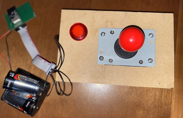
A home-made wireless game controller

ColecoVision Barn Find Gets Wireless Makeover

Few things are more satisfying than finding an old, forgotten piece of technology somewhere and bringing it back to life. And while it’s great to see a rare sports car or an Apollo Flight Computer being restored, even not-very-successful game consoles from the 1980s can make for some great repair stories. Just look at how [Discreet Mayor] describes his restoration and modification efforts on a ColecoVision that he literally found in a barn.

Given that the ColecoVision was on the market between 1982 and 1985, we can assume that [Discreet Mayor]’s console had been sitting on a shelf for at least three decades, and the machine was definitely showing its age. Several components had failed due to corrosion, including the clock crystal, a 7400 series logic chip and a capacitor in the power supply, but since these are all standard components it was rather straightforward to replace them.

The controllers however were sadly beyond repair. Replacing them with standard joysticks wasn’t really an option because the ColecoVision controllers included a numeric keypad, which was mainly used to select game options. Making something completely new was the way to go, and [Discreet Mayor] decided to go for a wireless system while he was at it. After all, he had already developed a modular wireless IoT system based on the IEEE 802.15.4 standard, which turned out to be a perfect fit for this system.

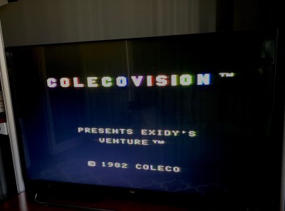
The splash screen of ColecoVision's Venture[Discreet Mayor] built a simple joystick-plus-fire-button setup on a piece of MDF and equipped it with his IoT transmitter. Instead of adding a replacement numeric keypad he decided to use the joystick to simulate the most commonly-used buttons: “right” for “1”, “down” for “2” and so on. The receiver module uses digital switches to mimic keypresses to the console’s input port. The end result might look a bit hacky, but the console is fully functional again and runs its games just like it did over thirty years ago.

We’ve seen several projects that add wireless controllers to a variety of classic consoles. If you’ve got a ColecoVision that turns out to be beyond salvaging, you can always just build your own from scratch.

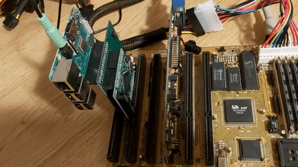
A 386 motherboard with a custom ISA card plugged in

Emulate Any ISA Card With A Raspberry Pi And An FPGA

One of the reasons the IBM PC platform became the dominant standard for desktop PCs back in the mid-1980s was its open hardware design, based around what would later be called the ISA bus. Any manufacturer could design plug-in cards or even entire computers that were hardware and software compatible with the IBM PC. Although ISA has been obsolete for most purposes since the late 1990s, some ISA cards such as high-quality sound cards have become so popular among retrocomputing enthusiasts that they now fetch hundreds of dollars on eBay.

So what can you do if your favorite ISA card is not easily available? One option is to head over to [eigenco]’s GitHub page and check out his FrankenPiFPGA project. It contains a design for a simple ISA plug-in card that hooks up to a Cyclone IV FPGA and a Raspberry Pi. The FPGA connects to the ISA bus and implements its bus architecture, while the Pi communicates with the FPGA through its GPIO ports and emulates any card you want in software. [eigenco]’s current repository contains code for several sound cards as well as a hard drive and a serial mouse. The Pi’s multi-core architecture allows it to run several of these tasks at once while still keeping up the reasonably high data rate required by the ISA bus.

In the videos embedded below you can see [eigenco] demonstrating the system on a 386 motherboard that only has a VGA card to hook up a monitor. By emulating a hard drive and sound card on the Pi he is able to run a variety of classic DOS games with full sound effects and music. The sound cards currently supported include AdLib, 8-bit SoundBlaster, Gravis Ultrasound and Roland MT-32, but any card that’s documented well enough could be emulated.

This approach could also come in handy to replace other unobtanium hardware, like rare CD-ROM interfaces. Of course, you could take the concept to its logical extreme and simply implement an entire PC in an FPGA.

Continue reading “Emulate Any ISA Card With A Raspberry Pi And An FPGA”