A home-made tape robot that stores VHS tapes

VHS Robot Swaps Tapes, As Seen In Hackers

Tape robots are typically used in places that store vast amounts of data – think film studios and government archives. If you’ve seen the 1995 cult movie Hackers, you might remember a scene where the main character hacks into a TV station and reprograms their tape ‘bot to load a series he wanted to watch. It’s this scene that inspired [Nathan] over at [Midwest Cyberpunk] to make his own tape robot that loads VHS tapes.

[Nathan] has thousands of tapes in his collection, but the robot is not built to manage all of them. Instead, it’s meant to help him run his VHS streaming channel, saving him from having to physically go to his VCR every time a tape needs swapping. For that, a ten-tape storage capacity is plenty.

A custom cyberdeck used to drive a tape robot
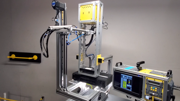
The main parts of the tape robot are a grabber that holds the tape, an extender that moves it forward and backward, and a linear rail that moves it up and down. The vertical motion is generated by a hybrid stepper motor through a belt drive system, while the grabber and extender are operated pneumatically. Once the grabber reaches the VCR, a pneumatic pusher shoves the tape inside. All of this is nearly identical to the robot seen in the movie, which was most likely not a commercial machine but a custom-made prop.

The whole system is controlled by an ESP32 running FluidNC inside the robot as well as a handmade cyberdeck next to it that manages the overall process of loading and storing tapes. Although [Nathan] is currently using the robot for his streaming channel, he’s planning to also use it for digitizing part of his massive tape collection, which contains a few titles that were never released on newer formats.

Working with old tapes can be tricky: some types of tape degrade over time, while others might come with primitive copy protection systems. But moving information over to newer media is a necessity if you don’t want to risk losing it forever.

Continue reading “VHS Robot Swaps Tapes, As Seen In Hackers

A small speaker with an LCD showing chatbot responses

AI-Powered Speaker Is A Chatbot You Can Actually Chat With

AI-powered chatbots are pretty cool, but most still require you to type your question on a keyboard and read an answer from a screen. It doesn’t have to be like that, of course: with a few standard tools, you can turn a chatbot into a machine that literally chats, as [Hoani Bryson] did. He decided to make a standalone voice-operated ChatGPT client that you can actually sit next to and have a conversation with.

The base of the project is a USB speaker, to which [Hoani] added a Raspberry Pi, a Teensy, a two-line LCD and a big red button. When you press the button, the Pi listens to your speech and converts it to text using the OpenAI voice transcription feature. It then sends the resulting text to ChatGPT through its API and waits for its response, which it turns into sound again through the eSpeak speech synthesizer. The LCD, driven by the Teensy, shows the current status of the machine and also provides live subtitles while the machine is talking.

To spice up the AI box’s appearance, [Hoani] also added an LED ring which shows a spectrogram of the audio being generated. This small addition really makes the thing come alive, turning it into what looks like a classic Sci-Fi movie prop. Except that this one’s real, of course – we are actually living in the future, with human-like AI all around us.

All code, mostly written in Go, is freely available on [Hoani]’s GitHub page. It also includes a separate audio processing library called toot that [Hoani] wrote to help him interface with the micophone and do spectral analysis. Anyone with basic electronic skills can now build their own AI companion and talk to it – something that ham radio operators have been doing for a while.

Continue reading “AI-Powered Speaker Is A Chatbot You Can Actually Chat With”

A schematic for a continuity tester that modulates its pitch based on the resistance measured

Op Amp Contest: Clever Continuity Tester Tells You Where The Problem Is

A continuity tester, as found on most multimeters today, is a great tool for finding broken connections and short circuits. But once you’ve found a short, it’s up to you to figure out which part of the circuit it’s in – a tedious job on a large PCB with hundreds of components. [John Guy] aims to ease this task with a continuity tester that modulates the beeper’s tone according to the resistance measured in the circuit. Tracking down a short circuit is then simply a matter of probing multiple points along a track and observing whether the pitch goes up or down.

The circuit is based on a single AD8534 quad op amp chip. The first stage measures the voltage across the circuit under test in response to small current and amplifies it. The resulting signal is fed into a voltage-controlled oscillator (VCO) made from one op amp connected as an integrator and another working as a comparator with hysteresis. Op amp number four amplifies the resulting square wave and drives a speaker. A low-pass filter makes the sound a bit more pleasing to the ears by removing the higher notes.

[John] paid particular attention to the PCB design to make it easy to assemble despite having a large number of SMD components on a small board. He even placed a parts list on the rear silkscreen, so anyone can assemble it even without the accompanying documents. The resulting board can be placed in a laser-cut acrylic case, turning it into a neat handheld instrument that will definitely find a place in any engineer’s toolbox. Measuring resistance through sound is not as accurate as using a full four-wire setup with an ohmmeter, but will be much faster and easier if you just want to find that annoying solder bridge hiding somewhere on your board.

An aluminium case with a small PCB and two nine-volt batteries inside

A Low-Noise Amplifier To Quantify Resistor Noise

Noise is all around us, and while acoustic noise is easy to spot using our ears, electronic noise is far harder to quantify even with the right instruments. A spectrum analyzer is the most convenient tool for noise measurements, but also adds noise of its own to whatever signal you’re looking at. [Limpkin] has been working on measuring very small noise signals using a spectrum analyzer, and shared his results in a comprehensive blog post.

The target he set himself was to measure the noise produced by a 50 Ohm resistor, which is the impedance most commonly seen on the inputs and outputs of RF systems. The formula for Johnson-Nyquist noise power tells us that the expected noise voltage in a one-hertz bandwidth is just 0.9 nanovolts – tiny by any standard, and an order of magnitude smaller than the noise floor of a typical spectrum analyzer. [Limpkin] therefore designed an amplifier and signal buffer to crank up the noise signal by a factor of 100, using ultra-low noise op amps running off a pair of nine-volt batteries.

There was a problem with this circuit, however: any stray DC voltage present at its input would also be amplified to levels that could damage the analyzer’s sensitive input port. To prevent this, [Limpkin] decided to add a clipper circuit to his amplifier. This consists of a pair of comparators that continuously monitor the amplifier’s output voltage and disconnect it through a silicon switch if it goes beyond 200 millivolts. [Limpkin] packaged his circuit in a beautifully-machined case and ran various tests to ensure the clipper worked reliably even in the presence of fast input transients.

With the clipper in place, it was safe to run the planned noise measurements. The end result? About 0.89 nV, just as predicted by theory. Measuring nanovolt-level signals usually requires extremely accurate equipment and lots of tricks to minimize noise. Sometimes though, noise is just what you need to make a radio transmitter. Thanks for the tip, [alfonso32]!

A first-generation car phone connected to a piece of prototype board with a BlueTooth module

Custom Bluetooth Adapter Brings 1990s Car Phone Back Online

[Jeff Lau]’s Mitsubishi 3000GT comes with all the essential features you’d expect in a fancy sports car from 1993: pop-up headlights, movable spoilers, and a fully-functional telephone handset in the center console. The phone was fully functional until North America’s first-generation AMPS cellular network was shut down back in 2008, since then, it hasn’t done much but show “NO SVC” on the display. That is, until [Jeff] decided to build a Bluetooth adapter that lets it connect to a modern smartphone.

The easy solution would have been to simply connect the handset’s speaker and microphone to a standard Bluetooth headset, but that would have destroyed the 1990s aesthetic it had going on. So what [Jeff] did instead was construct a plug-in module that hooks up to the phone’s base station in the trunk and communicates directly with all the existing systems. That way, the phone works in exactly the same way it always did: the radio is automatically muted during calls, the buttons on the steering column work as expected, and you can even dial and store numbers using the buttons on the handset.

A car phone base station and wiring in the trunk of a Mitsubishi 3000GT
No modifications required: the BlueTooth module is connected using the factory-installed cabling

It took a lot of reverse-engineering to figure out the technical details of the DiamondTel Model 92 that came with the car as a factory option. [Jeff] helpfully documented all of his findings on the project’s GitHub page, making it easy for anyone with a similar system to implement their own upgrades. The main components of the upgrade kit are a BM62 Bluetooth module that connects to a modern phone, a PIC18F27Q43 microcontroller to implement the car phone’s interface and menus, and several analog chips to process the audio. All of these are mounted on a piece of prototype board and housed in a standard plastic enclosure that neatly fits on top of the existing equipment in the trunk.

While the hardware mod is a pretty neat job already, the real strength of this project is in the software. [Jeff] worked hard to implement all relevant features and mimic the original interface as much as possible, even using 1G phone test equipment to simulate incoming calls from the long-gone network. He also added menu features to enable Bluetooth pairing, use voice assistants, and even play games including versions of Snake and Tetris stripped down to match the handset display’s constraints.

As classic phone conversions go, this is definitely one of the most impressive. [Jeff]’s extensive documentation should come in handy if you’ve got a similar model, but if you don’t, there’s still plenty of ways to connect modern electronics without defacing your classic ride’s interior.

Continue reading “Custom Bluetooth Adapter Brings 1990s Car Phone Back Online”

A milled PCB next to a woman wearing a dress that includes it

Elegant Evening Dress Sports Servo-Actuated Flowers

There’s been plenty of research into “smart fabrics”, and we’ve seen several projects involving items of clothing with electronics integrated inside. These typically include sensors and simple actuators like LEDS, but there’s no reason you can’t integrate moving electromechanical systems as well. [Rehana Al-Soltane] did just that: she made an elegant evening dress with flowers that open and close on command.

It took [Rehana] a bit of experimentation to figure out a floral design that opens and closes smoothly without crumpling the fabric or requiring excessive force to actuate. She finally settled on a plastic sheet sandwiched between two layers of fabric, with pieces of fishing line attached that pull the edges inward. The lines are guided through a tube down the back of the dress, where a servo pulls or releases them.

The mechanical flower can be operated by touch — [Rehana] made one of the other flowers conductive by embedding copper tape between its petals and connected it to the capacitive touch sensor interface of an Atmel microcontroller. The micro is sitting on a custom PCB that’s worn on the hip, with wires going to the servo at the back. You can see how the system operates in the video embedded below.

The dress is [Rehana]’s final project for the famous “How To Make (almost) Anything” course at MIT, and required a wide variety of skills: the cable guide was 3D printed, the flower petals were laser cut, the PCB was milled, and the end product was sewn together. [Rehana] has a knack for making electronics-infused clothes and accessories, including the flexible PCB crown that she’s wearing in the image above. Continue reading “Elegant Evening Dress Sports Servo-Actuated Flowers”

Classic Film Camera Goes Digital With Game Boy Tech

Despite having been technologically obsolete for a decade or two, analog photography is still practiced by hobbyists and artists to achieve a particular aesthetic. One might imagine a similar thing happening with early digital cameras, and indeed it has: the Game Boy Camera has seen use in dozens of projects. [Michael Fitzmayer] however decided to combine the worlds of analog and early digital photography by equipping a Holga with the image sensor from a Game Boy Camera.

A camera module and an STM32 module on a solderless breadboardThe Holga, if you’re not familiar, is a cheap film camera from the 1980s that has achieved something of a cult following among retro-photography enthusiasts. By equipping it with the sensor from what was one of the first mass-market digital cameras, [Michael] has created a rather unusual digital point-and-shoot. The user interface is as simple as can be: a single button to take a photo, and nothing else. There’s no screen to check your work — just as with film, you’ll have to wait for the pictures to come back from the lab.

The sensor used in the Game Boy Camera is a Mitsubishi M64282FP, which is a 128 x 128 pixel monochrome CMOS unit. [Michael] hooked it up to an STM32F401 microcontroller, which reads out the sensor data and stores it on an SD card in the form of a bitmap image.

With no film roll present, the Holga has plenty of space for all the electronics and a battery. The original lens turned out to be a poor fit for the image sensor, but with a bit of tweaking the Game Boy optics fit in its place without significantly altering the camera’s appearance.

A monochrome low-resolution selfie of a man making the peace sign[Michael] helpfully documented the design process and shared all source code on his GitHub page. Holgas shouldn’t be hard to find to find, but if none are available in your area you can just roll your own. The Game Boy Camera is actually one of the most versatile cameras out there, having been used for everything from video conferencing to astrophotography.