Linkage Inferring Software Handwaves Away The Hard Stuff

Jokes aside, manually designing linkages that move along specific paths is no easy task. Whether we’re doodling paper sketches or constraining lines in a CAD program, we still need to do the work of actually “imagining” the linkage design. If only there were some sort of tool that would do all that hard imagining work for us! Thankfully, we’re in luck! That’s exactly what researchers [Gen Nishida], [Adrien Bousseau2], and [Daniel G. Aliaga1] at Purdue have done. They’ve designed a software tool that lets us position important bodies in space in particular “key” frames, and then the software simply fills in the linkage for you!

To start the design process, the user inputs a few candidate locations that their solid bodies need to reach in the final linkage path.  From here, these locations get fed to a particle filter. This particle filter seeds thousands of semi-random linkage configurations at small timesteps, selects some of the best-matching ones that most closely approximate the required body locations, removes the lesser-scoring results, re-creates a new set of possible joint configurations based on the best matching ones, and repeats until the tool converges on a linkage that respects our input key frames.

Like a brute force search, this solution takes lots and lots of samples to find a solution, but unlike a brute force search, trials iteratively improve, enabling the software to converge closer and closer to a final solution. Under the hood, the software needs to actually simulate these candidate linkage in order to grade them. It’s in this step that the team wrote in additional checks to remove impossible linkages like self-intersecting joints from this linkage “gene pool” before reseeding them. The result is a tool that does all that trial-and-error scratchwork for you–no brain cycles. For more details, have a peek at their (open access!) paper.

Design software that augments our mechanical design capabilities is a rare gem on these pages, and this one is no exception. If your curious to play with other useful linkages simulating tools, have a go at Linkage Designer. And if you’re in the mood for other tools that fill in the blanks, check out this machine learning algorithm that literally fills in footage between frames in a video feed.

Continue reading “Linkage Inferring Software Handwaves Away The Hard Stuff”

Budget-Friendly Bend Sensor Deforms With Precision

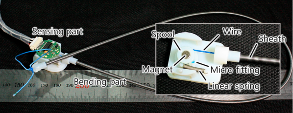
We’re pretty familiar with budget resistor-based bend sensors at this point, but this sensor is in a totally different class. Instead of relying on resistive elements, [Useok Jeong] and [Kyu-Jin Cho] devised a bend sensor that relies on geometric properties of the sensor itself. The result is a higher-fidelity measuring device made from a pretty widely available collection of stock parts.

We’ll admit, calling this device a bend sensor might be a bit of a stretch, so let’s dig into some of the operating principles. What we’re actually measuring is the accumulated angle, the sum of all the curvature deformations along the length of the sensing element. The sensor is made of 3 main pieces: an outer extension spring-based wire sheath; a flexible, tensioned inner wire core that’s fixed at one end; and a small displacement sensor that measures the length changes in the wire’s free end. The secret ingredient to making this setup work is a special property of the outer wire sheath or spring guide. Here, the spring guide actually resists being compressed while being bent.  Because the inner radius of the bend remains a constant length, the center wire core is forced to elongate. With the excess wire spooled up at the sensor base, we simply measure how much we collected, apply some math, and get a resulting angle! What’s more, the folks behind this trick also demonstrate that the length and angle relationship is linear with an R-square of 0.9969.

One of the best parts about this sensor is how reproducible it seems from from a modest collection of stock parts. Spring guide (aka: extension spring) is available from McMaster-Carr and DR Templeman, and that flexible core might be readily substituted with some wire rope.

It’s not everyday that new topologies for bend sensors pop into the world, let alone linear ones. To learn more, the folks behind the project have kindly made their research paper open access for your afternoon reading enjoyment. (Bring scratch paper!) Finally, if you’re looking for other bend-related sensors, have a look at this multi-bend measurement setup.

Continue reading “Budget-Friendly Bend Sensor Deforms With Precision”

The B-Sides: Curious Uses Of Off-the-Shelf Parts

I admit: a few years of prototyping without easy machine shop access really whets my tastebuds for turning metal chips. But all that time spent away from proper machine tools has also pushed me to re-imagine part catalogs, something I see almost every day. Without any precision metalworking tools handy, stock mechanical parts have become my supplement for complexity. And so a former dogma to machine-everything-thyself has been transformed into a hunt for that already-made-part-that-does-it-for-you.

But with part catalogs featuring tens of thousands of purpose-built parts, I started reimagining some of them for other misdeeds. And after a few years spent reinventing use cases for some of these parts, I’m about ready to tell you how to misuse them properly. So today I’d like to show you some of my favorite mechanical part B-sides, so to speak. These are ordinary parts in unorthodox places–something you surely won’t find in the datasheet! Now let’s have a look. Continue reading “The B-Sides: Curious Uses Of Off-the-Shelf Parts”

Re-imagining The Crossed Gantry 3D Printer

Simply having a few go-to 3D printer motion system designs is no reason to stop exploring them, as even small iterations on an existing architecture can yield some tremendous improvements. In the last few months, both [Annex_Engineering] and [wesc23] have been piloting a rail-derived crossed gantry architecture, a “CroXY” as it’s come to be known. Borrowing concepts from Ultimaker’s crossed gantry using rods, the Hypercube Overkill project, and perhaps even each other, the results are two compact machine frames capable of beautiful prints at extremely high speeds–upwards of 400 mm/sec in [Annex_Engineering’s] case!

Both gantry designs take a rotated MGN12 rail (a la the Railcore) and cross two of them, mounting the carriage at the intersection point much like an Ultimaker. Each crossed rail controls a degree of freedom with vanilla Cartesian kinematics, but each degree of freedom also has a redundant motor for added torque. Like the CoreXY design, this setup is tailored for clean prints at high speeds since the motion-related motors have been removed from the moving mass. However the overall belt length has been reduced tremendously, resulting in a much stiffer setup.

But the innovation doesn’t stop there. Both gantries also feature a unique take on a removable Z probe. When the machine needs to level the bed, it travels to a corner to “quickdraw” a magnetically attached limit switch from a holster. Once mounted, this probe becomes the lowest point on the carriage, allowing the carriage to travel around the bed probing points. When finished, the probe simply slots back into its holster, and the print can begin.

Both [wesc23’s] CroXY and a variant of [Annex_Engineering’s] K2 are up on Github complete with bills of materials if you’re curious to poke into the finer details. With commercial 3D printer manufacturers spending the last few years in a race to the bottom, it’s exciting to still see new design pattern contributions that push for quality and performance. For more design patterns contributions, have a look at [Mark Rehorst’s] Kinematically coupled bed design.

Continue reading “Re-imagining The Crossed Gantry 3D Printer”

E3D Teaches Additive 3D-Printers How To Subtract

We might’ve thought that extrusion based 3D printers have hit their peak in performance capabilities. With the remaining process variables being tricky to model and control, there’s only so much we can expect on dimensional accuracy from extruded plastic processes. But what if we mixed machines, adding a second machining process to give the resulting part a machined quality finish? That’s exactly what the folks at E3D have been cooking up over the last few years: a toolchanging workflow that mixes milling and 3D printing into the same process to produce buttery smooth part finishes with tighter dimensional accuracy over merely 3D printing alone.

Dubbed ASMBL (Additive/Subtractive Machining By Layer), the process is actually the merging of two complimentary processes combined into one workflow to produce a single part. Here, vanilla 3D printing does the work of producing the part’s overall shape. But at the end of every layer, an endmill enters the workspace and trims down the imperfections of the perimeter with a light finishing pass while local suction pulls away the debris. This concept of mixing og coarse and fine manufacturing processes to produce parts quickly is a re-imagining of a tried-and-true industrial process called near-net-shape manufacturing. However, unlike the industrial process, which happens across separate machines on a large manufacturing facility, E3D’s ASMBL takes place in a single machine that can change tools automatically. The result is that you can kick off a process and then wander back a few hours (and a few hundred tool changes) later to a finished part with machined tolerances.
What are the benefits of such an odd complimentary concoction, you might ask? Well, for one, truly sharp outer corners, something that’s been evading 3D printer enthusiasts for years, are now possible. Layer lines on vertical surfaces all but disappear, and the dimensional tolerances of holes increases as the accuracy of the process is more tightly controlled (or cleaned up!) yielding parts that are more dimensionally accurate… in theory.

But there are certainly more avenues to explore with this mixed process setup, and that’s where you come in. ASMBL is still early in development, but E3D has taken generous steps to let you build on top of their work by posting their Fusion 360 CAM plugin, the bill-of-materials and model files for their milling tool, and even the STEP files for their toolchanging motion system online. Pushing for a future where 3d printers produce the finer details might just be a matter of participating.

It’s exciting to see the community of 3D printer designers continue to rethink the capabilities of its own infrastructure when folks start pushing the bounds beyond pushing plastic. From homebrew headchanging solutions that open opportunity by lowering the price point, to optical calibration software that makes machines smarter, to breakaway Sharpie-assisted support material, there’s no shortage of new ideas to play with in an ecosystem of mixed tools and processes.

Have a look at ASMBL at 2:29 in their preview after the break.

Continue reading “E3D Teaches Additive 3D-Printers How To Subtract”

Bantam Tools PCB Mill Gets A Ferocious New Sequel

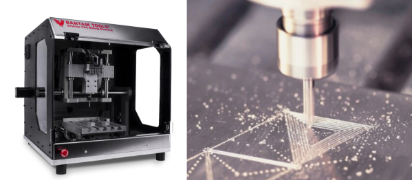
When the first Bantam Tools’ Milling Machine landed, it put PCB prototyping at the forefront with a smooth software and hardware pipeline for spinning out circuit boards in a manner of minutes. Now the folks at Bantam Tools are back, putting those insights into a new machine that makes cutting aluminum a first class feature. While machine details are still sparse from their announcement page, knowing that Bantam Tools has spent a few years turning classrooms of students into hardware prototypes reassures us that we’re in good hands. Now let’s spill some beans on this beast. Continue reading “Bantam Tools PCB Mill Gets A Ferocious New Sequel”

Dial In Your Multi-Headed 3D Printer With 2020 Machine Vision

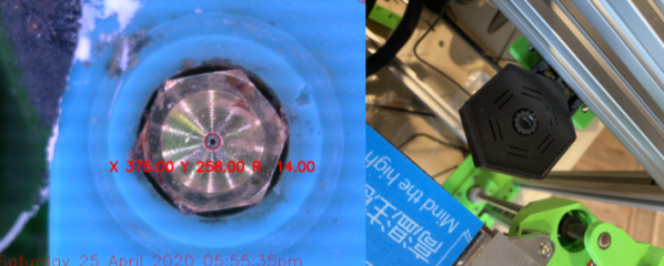
Most folks that have been poking around at multi-tool 3D printing know that lining up nozzles can be a gnarly, but necessary pain point. Existing methods either have us measure offsets with a vernier scale or with a series of pictures taken with an upwards-facing camera. And this step is not to be ignored! Any mismatch between nozzles, and your multicolor prints end up looking like Scotty really screwed up those sliders on that transporter beam console. Fear not, however! [Danal] took this problem as an opportunity to write something that’s completely automated and brought to you by some machine vision.

Dubbed TAMV, for Tool Align Machine Vision, [Danal] added a Raspberry Pi alongside his existing 3D printing motion controller in addition to an upwards facing camera. A few lines of code (and a few hours of compiling OpenCV) later, and he had himself a circle-detecting script that automatically cycles through each tool, detects the nozzle center, and calculates an offset for each tool that’s stored into the machine’s configuration file. If that’s not nifty enough, he’s made the entire setup open-source, and he included both an installation script for compiling OpenCV and a well-written set of step-by-step instructions.

In a world where most hobbyists approaches still solve this problem manually, this is leaps and bounds ahead of what we know, and it’s a great application of machine vision built on top of a stack of recognizable hardware and software. While this project was outfitted for a Jubilee running a Duet3 controller with a Raspberry Pi connected in “single-board computer” mode, the core features are readily adaptable to any other multi-tool machine with a similar control board stack. And for folks willing to poke under the hood, the project could even be extended to a standalone script that you can run on your PC locally to simply print the tool offsets separately.

Alongside TAMV, it’s refreshing that even a decade after 3D printers have been with us, we’re still finding ways to make these machines more capable. For more fresh hacks in this category, check out a new spin on using sharpie ink as a support material release agent.

Sadly, [Danal] has recently passed away in the last week, but we are grateful to capture a snapshot in the history of this person’s life.

Continue reading “Dial In Your Multi-Headed 3D Printer With 2020 Machine Vision”