Power Tool Battery Fume Extractor

A solder fume extractor is something we could probably all use. While there isn’t much to them, [Steven Bennett] put a lot of thought into making one that was better for him, and we admired his design process, as well as the extractor fan itself. You can see the finished result in the video below.

The electrical design, of course, is trivial. A computer fan, a switch, and a battery — in this case, a Makita power tool battery. But the Fusion 360 design for the 3D printed parts got a lot of thought to make this one of the best fume extractor fans we’ve seen.

Continue reading “Power Tool Battery Fume Extractor”

Measuring A Millisecond Mechanically

If you are manufacturing something, you have to test it. It wouldn’t do, for example, for your car to say it was going 60 MPH when it was really going 90 MPH. But if you were making a classic Leica camera back in the early 20th century, how do you measure a shutter that operates at 1/1000 of a second — a millisecond — without modern electronics? The answer is a special stroboscope that would look at home in any cyberpunk novel. [SmarterEveryDay] visited a camera restoration operation in Finland, and you can see the machine in action in the video below.

The machine has a wheel that rotates at a fixed speed. By imaging a pattern through the camera, you can determine the shutter speed. The video shows a high-speed video of the shutter operation which is worth watching, and it also explains exactly how the rotating disk combined with the rotating shutter allows the measurement. Continue reading “Measuring A Millisecond Mechanically”

The First Gui? Volscan Controls The Air

In the 1950s,  computers were, for the most part, ponderous machines. But one machine offered a glimpse of the future. The Volscan was probably the first real air traffic computer designed to handle high volumes of military aircraft operations. It used a light gun that looked more like a soldering gun than a computer input device. There isn’t much data about Volscan, but it appears to have been before its time, and had arguably the first GUI on a computer system ever.

The Air Force had a problem. The new — in the 1950s — jets needed long landing approaches and timely landings since they burned more fuel at lower altitudes. According to the Air Force, they could land 40 planes in an hour, but they needed to be able to do 120 planes an hour. The Whirlwind computer had proven that computers could process radar data — although Whirlwind was getting the data over phone lines from a distance. So the Air Force’s Cambridge Research Center started working on a computerized system to land planes called Volscan, later known as AN/GSN-3.

Continue reading “The First Gui? Volscan Controls The Air”

[Bunnie] Peeks Inside ICs With IR

If you want to see inside an integrated circuit (IC), you generally have to take the die out of the package, which can be technically challenging and often destroys the device. Looking to improve the situation, [Bunnie] has been working on Infra-Red, In Situ (IRIS) inspection of silicon devices. The technique relies on the fact that newer packages expose the backside of the silicon die and that silicon is invisible to IR light. The IR reflects off the bottom metalization layer and you can get a pretty good idea of what’s going on inside the chip, under the right circumstances.

As you might expect, the resolution isn’t what you’d get from, say, a scanning electron microscope or other techniques. However, using IR is reasonably cheap and doesn’t require removal from the PCB. That means you can image exactly the part that is in the device, without removing it. Of course, you need an IR-sensitive camera, which is about any camera these days if you remove the IR filter from it. You also need an IR source which isn’t very hard to do these days, either.

Do you need the capability to peer inside your ICs? You might not. But if you do and you can live with the limitations of this method, it would be a very inexpensive way to get a glimpse behind the curtain.

If you want to try the old-fashioned way, we can help. Just don’t expect to be as good as [Ken] at doing it right away.

Continue reading “[Bunnie] Peeks Inside ICs With IR”

Bode Plot Un-Lecture

[Rolinychupetin] insists that his recent video is not a lecture but actually a “recitation” about Bode plots. That may be, but it is still worth a watch if you want to learn more about the topic. You can see the video below.

If you haven’t run into Bode plots before, they are simple plots of magnitude or phase vs. frequency, usually plotted on a log scale. Named after Bell Lab’s [Hendrik Wade Bode], they are useful for understanding filters or anything with a frequency response.

Continue reading “Bode Plot Un-Lecture”

Pi Picos Give Casio FX9000P Its Memory Back

Is the Casio FX9000P a calculator or a computer? It’s hard to tell since Casio did make calculators that would run BASIC. [Menadue] didn’t know either, but since it had a CRT, a Z80, and memory modules, we think computer is a better moniker.

He found one of these, but as you might expect, it needed a bit of work. There were two bad video RAM chips on the device, and [Menadue] used two Raspberry Pi Picos running a program to make them think they are RAM chips. The number of wires connecting the microcontollers might raise some eyebrows, but it does appear to get the job done.

He also used more Picos to emulate memory on cartridges. Then he used a test clip and a — you guessed it — another Pico to monitor the Z80 bus signals. It is amazing that the Pico can replace what would have been state-of-the-art memory chips and a very expensive logic analyzer.

The second video mostly shows the computer in operation. The use of Picos to stand in for so much is clever. It reminded us of the minimal Z80 computer that used an Arduino for support chips. The computer itself, though, reminded us more of a cheap version of the HP9845.

Continue reading “Pi Picos Give Casio FX9000P Its Memory Back”

Assembly Language 80’s Minicomputer Style

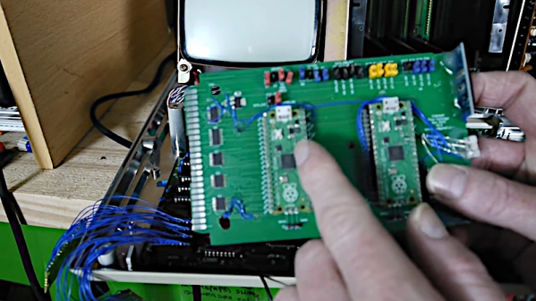
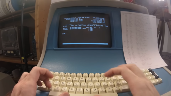
In the days before computers usually used off-the-shelf CPU chips, people who needed a CPU often used something called “bitslice.” The idea was to have a building block chip that needed some surrounding logic and could cascade with other identical building block chips to form a CPU of any bit width that could do whatever you wanted to do. It was still harder than using a CPU chip, but not as hard as rolling your own CPU from scratch. [Usagi Electric] has a Centurion, which is a 1980s-vintage minicomputer based on a bitslice processor. He wanted to use it to write assembly language programs targeting the same system (or an identical one). You can see the video below.

Truthfully, unless you have a Centurion yourself, the details of this are probably not interesting. But if you have wondered what it was like to code on an old machine like this, you’ll enjoy the video. Even so, the process isn’t quite authentic since he uses a more modern editor written for the Centurion. Most editors from those days were more like CP/M ed or DOS edlin, which were painful, indeed.

The target program is a hard drive test, so part of it isn’t just knowing assembly but understanding how to interface with the machine. That was pretty common, too. You didn’t have a lot of help from canned routines in those days. For example, it was common to read an entire block from a hard drive, tape, or drum and have to figure out what part of it you were actually interested in instead of, say, opening a file and reading a stream of characters.

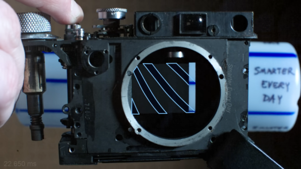
If nothing else, fast forward over to the 25-minute mark and see what a hard drive from that era looked like. Guess how much storage was on that monster? If you guessed more than 10 MB, you probably didn’t live through the 1980s. We won’t even guess what the price tag was, but you can bet it was spendy.

If you think entering programs like this is painful, try a front panel. That made paper tape seem like a great thing.

Continue reading “Assembly Language 80’s Minicomputer Style”