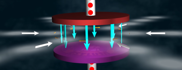
If you are like [The Science Asylum], you might wonder how a capacitor can work since, at their core, they are nothing more than a gap filled with air or another insulator. He explains how in a recent video you can see below.
Of course, at DC, a capacitor doesn’t conduct any better than the insulator used as its dielectric. However, a DC voltage has to start sometime and when it does, it briefly looks like AC. The video explains it all in simple terms. Of course, if you are math savvy, you can probably get as much out of the normal C=dQ/dV equation.
If that doesn’t speak to you, the explanation in the video about charges will shed some light. He even shows an animation of the classic “hydraulic model”, which is helpful to develop intuition about the process.
[G3OJV] knows the pain of trying to operate a ham radio transmitter on a small lot. His recent video shows how to put up a workable basic HF antenna in a small backyard. The center of the system is a 49:1 unun. An unun is like a balun, but while a balun goes from balanced line to an unbalanced antenna, the unun has both sides unbalanced. You can see his explanation in the video below.
The tiny hand-size box costs well under $40 or $50 and covers the whole HF band at up to 200 W. The video shows the inside of the box which, as you’d expect, is a toroid with a few turns of wire.
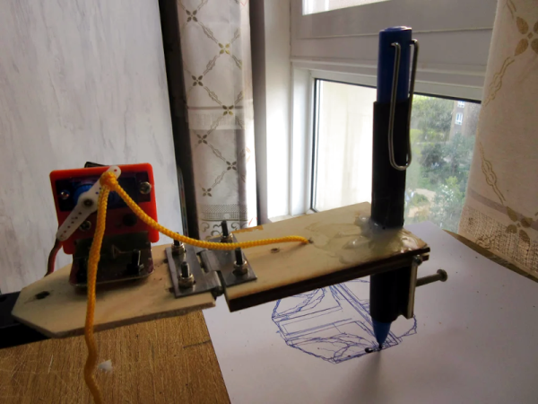
Although the widespread use of 3D printers has made things like linear bearings and leadscrews more common, you still can’t run down to your local big-box hardware store and get them. However, you can get drawer slides and any hobby shop can sell you some RC servos. That and an Arduino can make a simple and easy plotter. Just ask [JimRD]. You can also watch it do its thing in the video below.
Of course, servos aren’t usually what you use in a plotter. But the slides convert the rotation of the servo into linear motion. One servo for X and one for Y is all you need. Another microservo lifts the pen up and down using a hinge you could also get from a hardware store.
In an interesting post on Inverse, [Sarah Wells] does a deep dive into something you probably don’t think about very often: the blinking cursor. You’d assume there wasn’t much to the story. Maybe a terminal manufacturer put a toggle flip flop on the cursor output and it caught on. But the true story is much deeper than that.
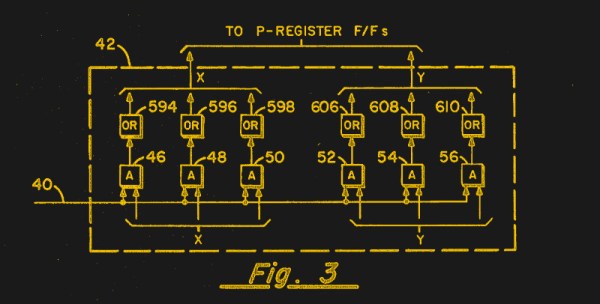
We were surprised that the father of the blinking cursor was one guy, [Charles Kiesling]. In a 1967 patent, he described the blinking cursor. An ex-Navy man, [Kiesling’s] patent names his employer at the time, Sperry Rand, where he’d worked since 1955.
In an ideal world, your FDM 3D printer’s bed would be perfectly parallel with the print head’s plane of movement. We usually say that means the bed is “level”, but really it doesn’t matter if it is level in the traditional sense, as long as the head and the bed are the same distance apart at every point. Of course, in practice nothing is perfect.
The second best situation is when the bed is perfectly flat, but tilted relative to the print head. Even though this isn’t ideal, software can move the print head up and down in a linear fashion to compensate for the tilt. Things are significantly worse if the bed isn’t itself flat, and has irregular bumps up and down all over.
To combat that, some printer firmware supports probing the bed to determine its shape, and adjusts the print head up and down as it travels across the map. Of course, you can’t probe the bed at every possible point, so the printer will have to interpolate between the measured reference points. Marlin’s bilinear bed leveling is an example.
But if you have enough flash space and you use Marlin, you may want to try unified bed leveling (UBL). This is like bilinear leveling on steroids. Unfortunately, the documentation for this mode is not as plain as you might like. Everything is out there, but it is hard to get started and information is scattered around a few pages and videos. Let’s fix that.
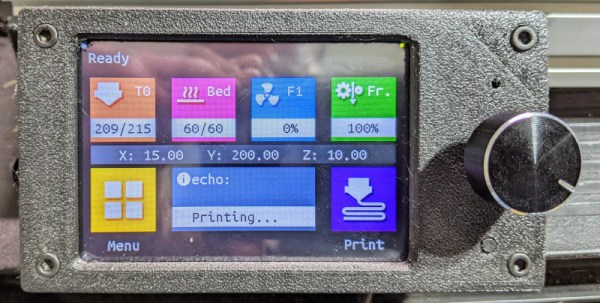
I was rebuilding one of my 3D printers — again — and decided I needed a display upgrade. A color screen is nice, but there are some limitations. I also found there are ways around these limitations, so I wanted to share my thoughts on a dual-mode color touch screen LCD controller for your 3D printer. The screen in question is a TFT35 from BigTree Tech. It is similar to an MKS screen, but it can operate in two different modes, as you will see.
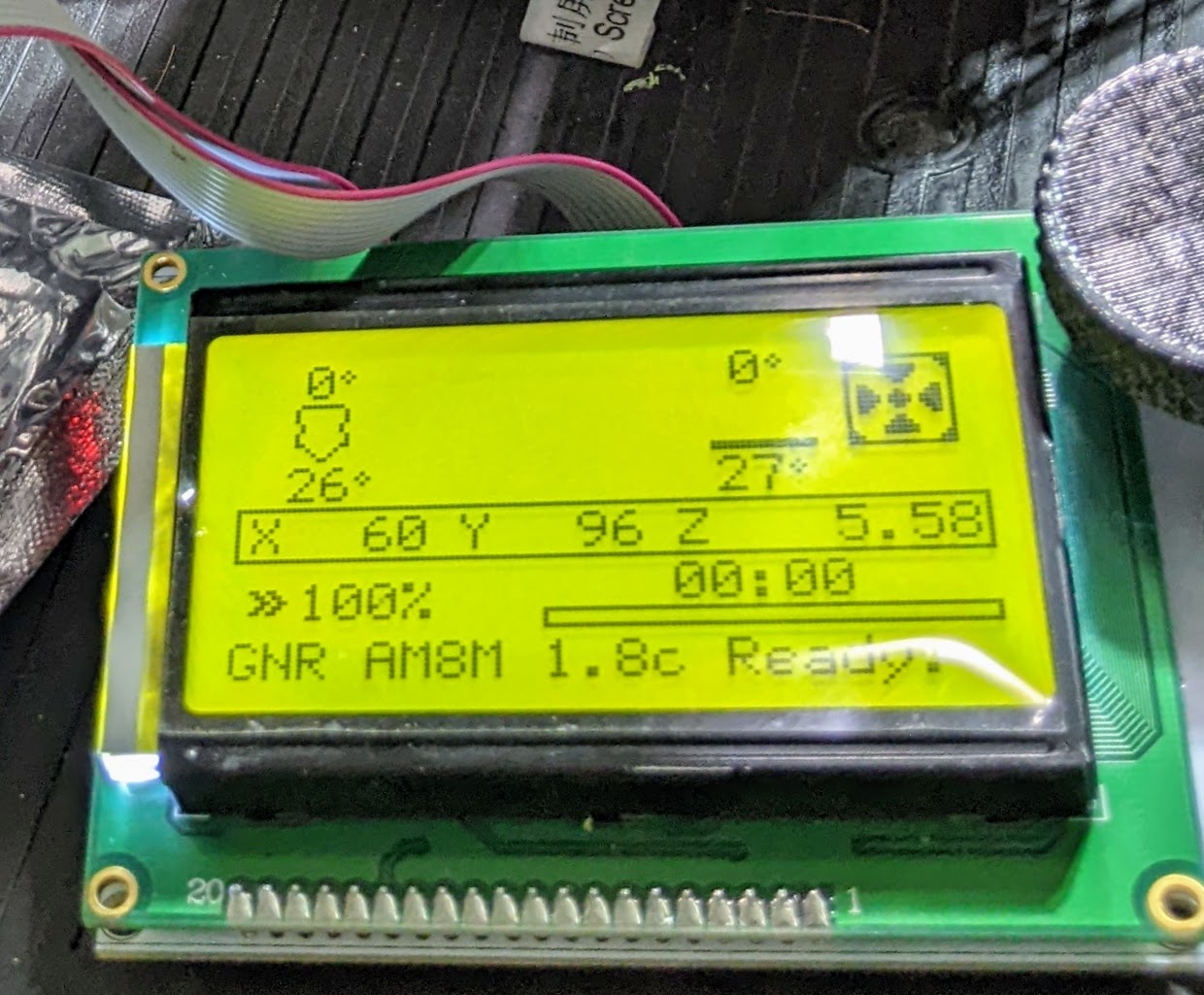
The more-or-less standard display for Marlin.
A few years ago, I picked up an Anet A8 which was very inexpensive, especially on sale. Not the best printer, though, because it has that cheap acrylic frame. No problem. A box full of aluminum extrusion later, the printer was reborn. Over time, I’ve completely reworked the extrusion system and the Y-axis, leaving only the motors, bearings, and the controller/display as the original.
That last part was what bothered me. The Anet board is actually pretty capable for a small cheap board. But it is just what the printer needs and nothing more. If you wanted to hack the printer there was very little memory left and only one spare pin for I/O. So it was time to replace the board and why not the controller, too?
The A8 has an LCD2004. That means it has a 20×4 LCD. Instead of an encoder knob, there are five buttons: basically up, down, left, right, and enter. Most printers now have an LCD12864 which, as you can probably guess, is a 128×64 LCD and they use an encoder knob for direction that you can push for the enter key.
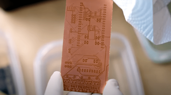
We always enjoy [Thomas Sanladerer’s] 3D printing videos. But his latest isn’t only about 3D printing. He shows how he uses a DLP printer — which has UV light, after all — to expose PC board blanks with great results. Honestly, once we heard the idea, we immediately saw how that could work it is surprising more people aren’t taking advantage of their DLP printers like that. Of course, [Thomas] does his usual thorough treatment of the topic.
Really, this isn’t exactly 3D printing even though it uses a 3D printer. Exposing boards with UV light and artwork is an old process that has been around for years, usually using transparency film and a UV light source. With a printer, you can create artwork digitally and the UV light source is already there.