[Mellow_Labs] picked up a few LiDAR matrix sensors and found them very exciting. While a normal time-of-flight sensor can accurately determine a range, the matrix sensor is like an array of 64 sensors that can build a 2D map of distances from 2 cm to 3.5 m. [Mellow] wanted to add the sensor to his robot to help it see what was in front of it. You can see how it worked out in the video below.
The robot in question is Zippy, a 3D printed tank-like robot with an ESP32. By default, the robot requires control inputs, but using the sensor will enable autonomous operation. For good or ill, the sensor mounted to Zippy was seeing the floor with about half of the rows. That means about 50% of the data went to waste. However, we think having a robot be able to see the floor in front of it might be a good thing.
[Mellow] used an LLM to write most of the code, so there were a number of iterations required to get things working. This required decimating even more of the data from the sensor. Still, pretty impressive.
Fire arrow versus the recreated fire dart. (Credit: Tod’s Workshop, YouTube)
The Mary Rose was a carrack in the English Tudor Navy of King Henry VIII that fought in multiple battles during the 16th century before it was sunk in 1545. After its wreck was located in 1971 and raised in 1982 the ship and all the items contained within the partially preserved hull became the focus of intense study. Among these items are the weaponry found, including the cannons, but also massive darts that seemed to have been designed for an incendiary payload. Recently [Tod’s Workshop] collaborated with others to test these presumed incendiary darts.
Although fire arrows have been around for a while, seeing what appears to be super-sized versions of these is somewhat unusual, but could make sense in taking out enemy ships of the time. The main questions are how you would even fire them, and how effective they would be. Were the darts thrown by hand from e.g. the crow’s nest, or fired from a cannon?
The reproduction darts used are based on the recovered remnants of the original darts, with an incendiary mixture inside a pitch-covered cloth covering. This mixture would be ignited by wooden fuses after a set amount of time, at which point the resulting fire would be basically impossible to put out. Obviously, this also means that if you were to throw one of these darts, it can absolutely not fall onto your own ship.
First tested was throwing the dart by hand, which seems like it would clear the ship. Of course, the three recovered darts were found near a rather special cannon that appeared to be both a miscast and angled upwards. Whether that cannon was used for launching apparently somewhat experimental darts is hard to say, but it can be tested. Sadly, lacking a full-sized black powder cannon a scale model dart was fired using compressed air.
From that scale test it’s clear that at full charge the dart would disintegrate due to the rapid acceleration, but a ‘soft’, or reduced, charge could work against nearby targets. Once the dart lodges itself into the enemy ship’s structure, it would definitely cause severe damage as further tests in the video demonstrate. Having a salvo of these fire darts fired at you from a nearby ship would definitely make for a pretty bad day.
If you’ve watched a Saturn V launch, you’ve probably seen how a large rocket will often jettison a stage on the way up. There are several reasons for this — there is no reason to haul an empty fuel container, for example. However, you can probably imagine how the separation works. You release something — probably explosive bolts — and gravity pulls the old stage away from you as you climb on the next stage’s engines. But what about on the way back? The command module drops the service module before reentry. [Apollo11Space] has a video explaining just how complicated that was to pull off. You can watch it below.
The main problem? The service module has almost everything you need: oxygen, a big engine, fuel, and electrical generation capability. If you’ve ever seen a real command module, they are tiny. Somehow, you need to get the command module prepared to be on its own for the amount of time it takes to land, and get the service module safely away.
If you’ve been interested in FreeCAD but haven’t known where to start, here’s a wonderful video tutorial for FreeCAD 1.1 by [Deltahedra] aimed squarely at how to model a 3D part from scratch while also following best engineering practices for part design. It focuses on a concise and meaningful workflow that respects your time and doesn’t make assumptions about skill level. It even starts by taking a few moments to explain how to navigate the interface, a courtesy many will appreciate.
FreeCAD can do quite a lot, so a tutorial that focuses on a specific yet broadly-applicable task with a clear context is a great way to narrow the scope into something manageable, and be comprehensive without getting bogged down in minutiae. [Deltahedra] does this by exclusively using the part design workbench, demonstrating what to do to make a part step-by-step, and showing common mistakes that can happen and how to fix them if they occur. Beyond that, it’s left up to the curious hacker to delve for themselves into what else FreeCAD has to offer.
Since 1.1 is (at this writing) the latest stable release, one can also be confident that the tutorial will match the user interface and features one sees on their own screen. After all, it can be frustrating to attempt to follow a tutorial only to find out things are a few versions behind and nothing is where one expects it to be.
Best practices aren’t just fussy rules about how to do things, and [Deltahedra] demonstrates this by showing how certain procedures just plain make more sense when designing shapes. Our own Arya Voronova has also shared best practices for FreeCAD, so check that out for some added perspective. You’ll be wielding FreeCAD in confidence and comfort in no time.
As time marches on, the retro gaming community gets more and more access to older systems. This is partially a product of modern computing having much more power to emulate more demanding systems, but also because many in the community have spent more time with their favorite systems. Such is the case for [tschicki] who has spent considerable time and effort reverse engineering the Playstation 2 to come up with this custom mainboard for a handheld version that still uses some of the original chips from the console.
This Playstation 2 handheld console is designed almost completely from the ground up, not just including the impressive main board but also its modernized features, including USB power delivery handled by an RP2040, digital video output, support for modern storage media like SD cards, a customized boot ROM, and upgraded audio. The DualShock 2 controller is also implemented within the handheld, and the case itself is designed to be 3D printed. It’s an impressive effort which preserves the original feel of the console without relying too much on ancient hardware for everything.
Before jumping in to building one yourself, though, [tschicki] cautions that this project is not for the faint of heart, as it requires some specilized tools and a high degree of skill, but for those still wishing to attempt this build all of the instructions are available on the project site. For such a popular console it’s no surprise we’ve seen plenty of other handheld PS2s before, from this one which uses an original PS2 mainboard to this one we featured way back in 2010.
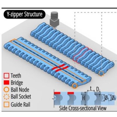
Along with Velcro, zippers have become an integral part of every day life, being a quick and easy way to usually temporarily join fabric together. Which isn’t to say that you cannot do more with the basic zipper concept, including using them to turn floppy 2D shapes into rigid 3D ones, such as with the Y-zipper concept proposed and demonstrated by [Jiaji Li] et al.
Although not a fully new idea, the Y-zipper is compared with a range of similar mechanisms that do not feature the same abilities, including the standard zipper ease of zipping up, the possibility of having curved geometry and automatic actuation.
Plus there is that the Y-zipper is designed from the start to be 3Dprinted, while still following the same basic pattern of interlocking teeth that the slider mechanism alternately pushes together or pulls apart.
By modifying the basic straight design of the flat strips, the resulting zipped-up form can take on a distinct bend, as well as turn into a coil or a screw. With a demonstrated joint design it is then possible to join multiple Y-zipper rods together, which could make for an interesting alternative to traditional pop-up tent supports, for example.
Also demonstrated is the use of TPU to create compliant bridges, as well as the direct integration of fabric, to show the versatility of the technology. With the used materials (PLA, TPU) the researchers estimate a maximum viable length of about 3 meters before the printed structures begin to disintegrate.
You’ve probably seen a Foucault pendulum in a museum. This Victorian-era science demonstration is named after physicist Léon Foucault and shows how the Earth rotates compared to a pendulum moving in a fixed plane. [RyanCreates] shows you how you can make your own, and it is surprisingly simple.
All you need is a heavy weight like a small mushroom anchor, fishing line, and a swivel — all things you can pick up at any sporting goods store. You’ll need a way to suspend it all, such as an eye hook in the ceiling.
In addition to the mechanical parts, the build calls for a camera to record the results and a lighter or other source of flame. The reason? To release the pendulum, you burn a thread that prevents it from swinging. This allows for a clean release with no sideways force.
The amount of your rotation depends on your latitude. At 33 degrees north, for example, you can expect 360*sin(33)/24 or 8.17 degrees per hour of rotation. [Ryan] measured a somewhat larger number, which was probably due to an error source, especially since he is measuring the angle using captured camera frames in Photoshop. That has to introduce some error, and small pendulums like this are incredibly sensitive to errors.
If you try it and find the source of the error, we’re sure [Ryan] would love to hear from you. Museum pieces are typically much larger, have ultra-low-friction pivots, and use electromagnets to keep the pendulum moving since, after all, even a Foucault pendulum can’t run forever.