Raspberry Pi Driven Polargraph Exhibits High Precision Drawing Ability

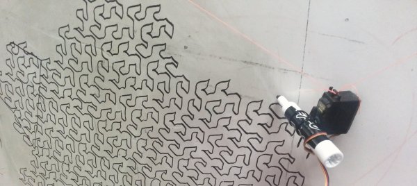
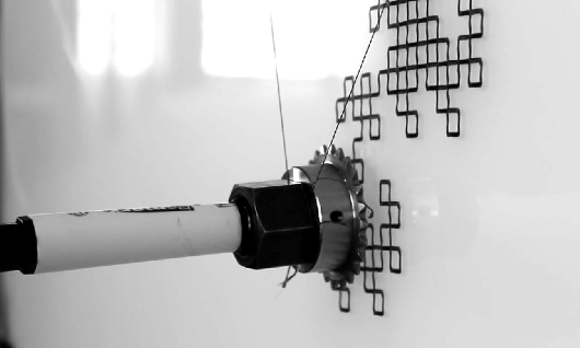
This polar graph draws some amazing shapes on a dry erase board. Part of that is due to the mounting brackets used for the two stepper motors and the stylus. But credit is also due for the code which takes velocity into account in order to plan for the next set of movements.

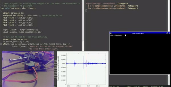
The Go language is used to translate data into step commands for the two motors. This stream of commands is fed over a serial connection between the RPi board and an Arduino. The Arduino simply pushes the steps to the motor controllers. The inclusion of the RPi provides the horsepower needed to make such smooth designs. This is explained in the second half of [Brandon Green’s] post. The technique uses constant acceleration, speed, and deceleration for most cases which prevents any kind of oscillation in the hanging stylus. But there are also contingencies used when there is not enough room to accelerate or decelerate smoothly.

You can catch a very short clip of the hardware drawing a tight spiral in the video embedded after the break.

Continue reading “Raspberry Pi Driven Polargraph Exhibits High Precision Drawing Ability”

A Polar Coordinate CNC Plotter Even Descartes Could Love

Take apart a few old DVD drives, stitch them together with cable ties, add a pen and paper, and you’ve got a simple CNC plotter. They’re quick and easy projects that are fun, but they do tend to be a little on the “plug and chug” side. But a CNC plotter that uses polar coordinates? That takes a little more effort.

The vast majority of CNC projects, from simple two-axis plotters to big CNC routers, all tend to use Cartesian coordinate systems, where points on a plane are described by their distances from an origin point on two perpendicular axes. Everything is nice and square, measurements are straightforward, and the math is easy. [davidatfsg] decided to level up his CNC plotter a bit by choosing a polar coordinate system, with points described as a vector extending a certain distance from the origin at a specified angle. Most of the plotter is built from FischerTechnik parts, with a single linear axis intersecting the center point of a rotary drawing platform. Standard G-code is translated to polar coordinates by a Java applet before being sent to a custom Arduino controller to execute the moves. Check out the video below; it’s pretty mesmerizing to watch, and we can’t help but wonder how a polar 3D-printer would work out.

Have polar coordinates got you stumped? It can be a bit of an adjustment from Cartesian space for sure. It can be worth it, though, showing up in everything from cable plotters to POV fidget spinners and even to color space models.

Continue reading “A Polar Coordinate CNC Plotter Even Descartes Could Love”

Cable Bots, Arise! Domination Of The Universe Is At Hand

Most CNC robots people see involve belts and rails, gantries, lead screws, linear bearings, and so forth. Those components need a rigid chassis to support them and to keep them from wobbling during fabrication and adding imperfections to the design. As a result, the scale is necessarily small — hobbyist bots max out at cabinet-sized, for the most part. Their rigid axes are often laid out at Cartesian right angles.

One of the exceptions to this common configuration is the delta robot. Deltas might be the flashiest of CNC robots, moving the end effector on three arms that move to position it anywhere in the build envelope. A lot of these robots are super fast and precise when charged with carrying a light load, and they get put to work as pick-and-place machines and that sort of thing. It doesn’t hurt that delta bots are also parallel manipulators, which means that the motors work together to move the end effector, with one motor pulling while the matching motor pulls.

But while Cartesian CNC bots are sturdy workhorses, and deltas are fly-weight racehorces, neither can really cut it when you want to go gigantic. In terms of simplicity and scale, nothing beats cable bots.

Cable Bots

Cable bots use wires or strings pulled by reel-mounted motors, with dimensions limited only by the room to mount the motors and the tensile strength of the cables used. When the strings are tensioned you can get a surprising degree of accuracy. Why not? Are they not computer-controlled motors? As long as your kinematic chain accounts for the end effector’s movement in one direction by unwinding another cable (for instance) you can very accurately control the end effector over a very wide scale.

The following are some fun cable bots that have caught my eye.

Continue reading “Cable Bots, Arise! Domination Of The Universe Is At Hand”

3D Cable Robot Uses The Building As Its Exoskeleton.

There’s not much information about this commercial product, but it looks so interesting, we just had to share it. It doesn’t seem there is anything too magical happening here: some motors (presumably some type of servo or stepper with positioning feedback) some cables and pulleys, and an end effector of your choosing. Oh, and just some clever math to solve the inverse kinematics – not that inverse kinematics is all that easy! You can see the robot at work in the video after the break.

Most likely you’ve already seen the end results of such a three-dimensional cable driven system on your TV. If you’re a fan of most field sports, the SkyCam system is what’s used to deliver the stunning aerial shots that really put you into the game. We’ve covered this sort of mechanism before, but only in two dimensions. Usually we see the concept used as a white-board plotter like this extremely methodical Polargraph or one built with K’NEX.

We can’t help but wonder how this might be adapted into other situations?  Perhaps, you could use small light-weight cables (fishing line) and pulleys to make a living-room beer delivery system or TV remote retrieval claw?  Or could it become the mechanics of a really large format 3D printer? If any of you do rig up some sort of house-hold beverage fetching robot, be sure to let us know via the tipline.

Continue reading “3D Cable Robot Uses The Building As Its Exoskeleton.”

A Tutorial On Using Linux For Real-Time Tasks

[Andreas] has created this tutorial on real-time (RT) tasks in Linux. At first blush that sounds like a rather dry topic, but [Andreas] makes things interesting by giving us some real-world demos using a Raspberry Pi and a stepper motor. Driving a stepper motor requires relatively accurate timing. Attempting to use a desktop operating system for a task like this is generally ill-advised. Accurate timing is best left to a separate microcontroller. This is why we often see the Raspi paired with an Arduino here on Hackaday. The rationale behind this is not often explained.

[Andreas] connects a common low-cost 28BYJ-48 geared stepper motor with a ULN2003 driver board to a Raspberry Pi’s GPIO pins. These motors originally saw use moving the louvers of air conditioners. In general, they get the job done, but aren’t exactly high quality. [Andreas] uses a simple program to pulse the pins in the correct order to spin the motor. Using an oscilloscope, a split screen display, and a camera on the stepper motor, [Andreas] walks us through several common timing hazards, and how to avoid them.

The most telling hazard is shown last. While running his stepper program, [Andreas] runs a second program which allocates lots of memory. Eventually, Linux swaps out the stepper program’s memory, causing the stepper motor to stop spinning for a couple of seconds. All is not lost though, as the swapping can be prevented with an mlockall() call.

The take away from this is that Linux is not a hard real-time operating system. With a few tricks and extensions, it can do some soft real-time tasks. The best solution is to either use an operating system designed for real-time operation, or offload real-time operations to a separate controller.

Continue reading “A Tutorial On Using Linux For Real-Time Tasks”

Hanging Plotter With A Color Twist

hangbot

[Jack Boland], a mechanical engineer at the University of Wisconsin, built a cool hanging plotter project called HangBot. It’s a fairly standard setup, where he converts an image to G-Code files, and it is plotted using two stepper motors for control. We’ve seen vertical plotters before, but they tend to only have a single pen. [Jack] expanded this one to bring color into the mix by splitting an image into separate CMYK layers, and plotting each onto separate transparency film. When overlaid, they create something close to a full color image. His idea is to use this setup as a replacement for typical window signage.

Since it’s drawing a continuous line, he appears to be employing a grid instead of a traditional dot pattern. That, combined with the inaccuracy of a marker tip means resolution will be limited. Still, you can tell that he’s made a great start in this (albeit blurry) photo. Check out the video of it’s operation after the break.

Continue reading “Hanging Plotter With A Color Twist”

Drawing Things Very Slowly, Very Easily

A while back, we saw [Euphy]’s polar pen plotter project. The mechanics of the build are very simple – just a pair of motors attached to a pen by a beaded cord. Even though the build is very simple, it’s possible to create awesome works of art albeit very slowly.

Since we featured [Euphy]’s polar pen plotter, a lot of improvements have been made. Now the Polargraph has an SD card slot for computer-less printing, a touch screen for manual control of the plotter, and a few new drawing styles that improve on the previous version a lot.

Right now the improved version of the Polargraph is set up in the front of a graffiti art supply shop in Edinburgh where it spends its time slowly drawing a window dressing. [Euphy] put up a few videos of what the Polargraph is capable of doing, very impressive and we hope he gets a few more PCBs in soon.

Continue reading “Drawing Things Very Slowly, Very Easily”