Test Your ‘Blue Pill’ Board For A Genuine STM32F103C8 MCU

With the market for STM32F103C8-based ‘Blue Pill’ boards slowly being overrun with boards that contain either a cloned, fake or outright broken chip, [Terry Porter] really wanted to have an easy, automated way to quickly detect whether a new board contains genuine STM32 silicon, or some fake that tries to look the part. After more than a year of work, the Blue Pill Diagnostics project is now ready for prime time.

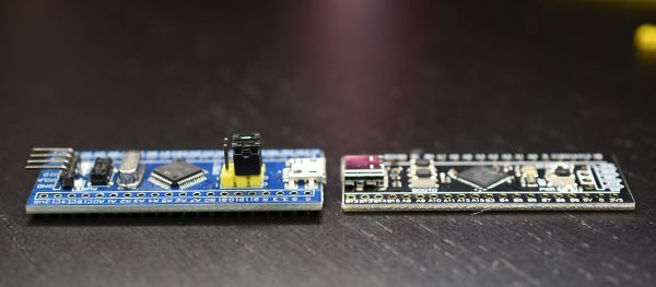
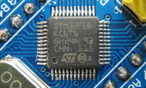
We have covered those clone MCUs previously. It’s clear that some of those ‘Blue Pill’ boards obviously do not have a genuine STM32 MCU on them, as they do not have the STM32 markings on them, while others fake those markings on the package and identifying can be hard to impossible. Often only testing the MCU’s actual functionality can give clarity on whether it’s a real STM32 MCU.

These diagnostics allow one to test not only the 64 kB of Flash, but also the 64 kB of ‘hidden’ Flash that’s often found on these MCUs (rebadged 128 kB STM32F103 cores). It further checks the manufacturer JDEC code and uses a silicon bug in genuine STM32F1xx MCUs where the BGMCU_IDCODE cannot be read without either SWD or JTAG connected.

Another interesting feature of Blue Pill Diagnostics is using Mecrisp-Stellaris Forth as its foundation, which allows for easy access to a Forth shell via this firmware as well, not unlike MicroPython and Lua, only in a fraction of the Flash required by those. We have previously written about using Mecrisp-Stellaris in your projects.

Blue Pill Vs Black Pill: Transitioning From STM32F103 To STM32F411

For many years now, the so-called ‘Blue Pill’ STM32 MCU development board has been a staple in the hobbyist community. Finding its origins as an apparent Maple Mini clone, the diminutive board is easily to use in breadboard projects thanks to its dual rows of 0.1″ pin sockets. Best of all, it only costs a few bucks, even if you can only really buy it via sellers on AliExpress and EBay.

Starting last year, boards with a black soldermask and an STM32F4 Access (entry-level) series MCUs including the F401 and F411 began to appear. These boards with the nickname ‘Black Pill’ or ‘Black Pill 2’. F103 boards also existed with black soldermask for a while, so it’s confusing. The F4xx Black Pills are available via the same sources as the F103-based Blue Pill ones, for a similar price, but feature an MCU that’s considerably newer and more powerful. This raises the question of whether it makes sense at this point to switch to these new boards.

Our answer is yes, but it’s not entirely clearcut. The newer hardware is better for most purposes, really lacking only the F103’s dual ADCs. But hardware isn’t the only consideration; depending on one’s preferred framework, support may be lacking or incomplete. So let’s take a look at what it takes to switch. Continue reading “Blue Pill Vs Black Pill: Transitioning From STM32F103 To STM32F411”

It’s SSB, But Maybe Not Quite As You Know It

Single Sideband, or SSB, has been the predominant amateur radio voice mode for many decades now. It has bee traditionally generated by analogue means, generating a double sideband and filtering away the unwanted side, or generating 90 degree phase shifted quadrature signals and mixing them. More recent software-defined radios have taken this into the CPU, but here’s [Georg DG6RS] with another method. It uses SDR techniques and a combination of AM and FM to achieve polar modulation and generate SSB. He’s provided a fascinating in-depth technical explanation to help understand how it works.

The hardware is relatively straightforward; an SI5351 clock generator provides the reference for an ADF4351 PLL and VCO, which in turn feeds a PE4302 digital attenuator. It’s all driven from an STM32F103 microcontroller which handles the signal processing. Internally this means conventionally creating I and Q streams from the incoming audio, then an algorithm to generate the phase and amplitude for polar modulation. These are fed to the PLL and attenuator in turn for FM and AM modulation, and the result is SSB. It’s only suitable for narrow bandwidths, but it’s a novel and surprisingly simple deign.

We like being presented with new (to us at least) techniques, as it never pays to stand still. Meanwhile for more conventional designs, we’ve got you covered.

A Digital Replacement For Your Magic Eye

Magic Eye tubes were popular as tuning guides on old-school radio gear. However, the tubes, the 6U5 model in particular, have become rare and remarkably hard to come by of late. When the supply dried up, [Bjørner Sandom] decided to build a digital alternative instead.

The build relies on a small round IPS display, measuring an inch in diameter and with a resolution of 128×115 pixels. One can only presume it’s round but not perfectly so. It was then fitted with a 25mm glass lens in order to give it a richer, deeper look more akin to a real Magic Eye tube. In any case, a STM32F103CBT was selected to drive the display, with the 32-bit ARM processor running at a lovely 72 MHz for fast and smooth updates of the screen.

The screen, controller, and supporting circuitry are all built onto a pair of PCBs and installed in a 3D-printed housing that lives atop a tube base. The idea is that the build is a direct replacement for a real 6U5 tube. The STM32 controller receives the automatic gain control voltage from the radio set it’s installed in, and then drives the screen to behave as a real 6U5 tube would under those conditions.

By virtue of the smart design, smooth updates, and that nifty glass lens, the final product is quite a thing to behold. It really does look quite similar to the genuine article. If you’ve got a beloved old set with a beleagured magic eye, you might find this a project worth replicating. Video after the break.

Continue reading “A Digital Replacement For Your Magic Eye”

Linux Fu: Failing Pipelines

Bash is great for automating little tasks, but sometimes a little script you think will take a minute to write turns into a half hour or more. This is the story of one of those half-hour scripts.

I have too many 3D printers. In particular, I have three that are almost — but not exactly — the same, so each one has a slightly different build process when I want to update their firmware. In all fairness, one of those printers is heading out the door soon, but I’ll probably still wind up building firmware images for it.

My initial process was painful. I have a special directory with the four files needed to configure Marlin for each machine. I copy all four files and ask PlatformIO to perform the build. Usually, it succeeds and gives me a file that looks like firmware-yyyyddmmhhmm.bin or something like that.

The problem is that the build process doesn’t know which of the three machines is the target: Sulu, Checkov, or Fraiser. (Long story.) So, I manually look at the file name, copy it, and rename it. Of course, this is an error-prone process, and I’m basically lazy, so I decided to write a script to do it. I figured it would take just a minute to bundle up all the steps. I was wrong.

Continue reading “Linux Fu: Failing Pipelines”

STM32 Offers Performance Gains For DIY Oscilloscope

There’s no shortage of cheap digital oscilloscopes available today from the usual online retailers, but that doesn’t mean the appeal of building your own has gone away — especially when we have access to powerful microcontrollers that make it easier than ever to spin up custom gear. [mircemk] is using one of those microcontrollers to build an improved, pocket-sized oscilloscope.

The microcontroller he’s chosen is the STM32F103C8T6, part of the 32-bit STM family which has tremendous performance compared to common 8-bit microcontrollers for only a marginally increased cost. Paired with a small 3-inch TFT color display, it has enough functions to cover plenty of use cases, capable of measuring both AC and DC signals, freezing a signal for analysis, and operating at an impressive 500 kHz at a cost of only around $15. The display also outputs a fairly comprehensive analysis of the incoming signal as well, with the small scope capable of measuring up to 6.6 V on its input.

This isn’t [mircemk]’s first oscilloscope, either. His previous versions have used Arduinos, generally only running around 50 kHz. With the STM32 microcontroller the sampling frequency is an order of magnitude higher at 500 kHz. While that’s not going to beat the latest four-channel scope from Tektronix or Rigol, it’s not bad for the form factor and cost and would be an effective scope in plenty of applications. If all you have on hand is an 8-bit microcontroller, though, we have seen some interesting scopes built with them in the past.

Simple STM32 Frequency Meter Handles Up To 30MHz With Ease

[mircemk] had previously built a frequency counter using an Arduino, with a useful range up to 6 MHz. Now, they’ve implemented a new design on a far more powerful STM32 chip that boosts the measurement range up to a full 30 MHz. That makes it a perfect tool for working with radios in the HF range.

The project is relatively simple to construct, with an STM32F103C6 or C8 development board used as the brains of the operation. It’s paired with old-school LED 7-segment displays for showing the measured frequency. Just one capacitor is used as input circuitry for the microcontroller, which can accept signals from 0.5 to 3V in amplitude. [mircemk] notes that the circuit would be more versatile with a more advanced input circuit to allow it to work with a wider range of signals.

It’s probably not the most accurate frequency counter out there, and you’d probably want to calibrate it using a known-good frequency source once you’ve built it. Regardless, it’s a cheap way to get one on your desk, and a great way to learn about measuring and working with time-varying signals. You might like to take a look at the earlier build from [mircemk] for further inspiration. Video after the break.

Continue reading “Simple STM32 Frequency Meter Handles Up To 30MHz With Ease”