Installing solar power at a home is a great way to reduce electricity bills, especially as the cost of solar panels and their associated electronics continue to plummet. Not every utility allows selling solar back to the grid, though, so if you’re like [Rogan] who lives in South Africa you’ll need to come up with some clever tricks to use the solar energy each day while it’s available to keep from wasting any. He’s devised this system for his water heater that takes care of some of this excess incoming energy.
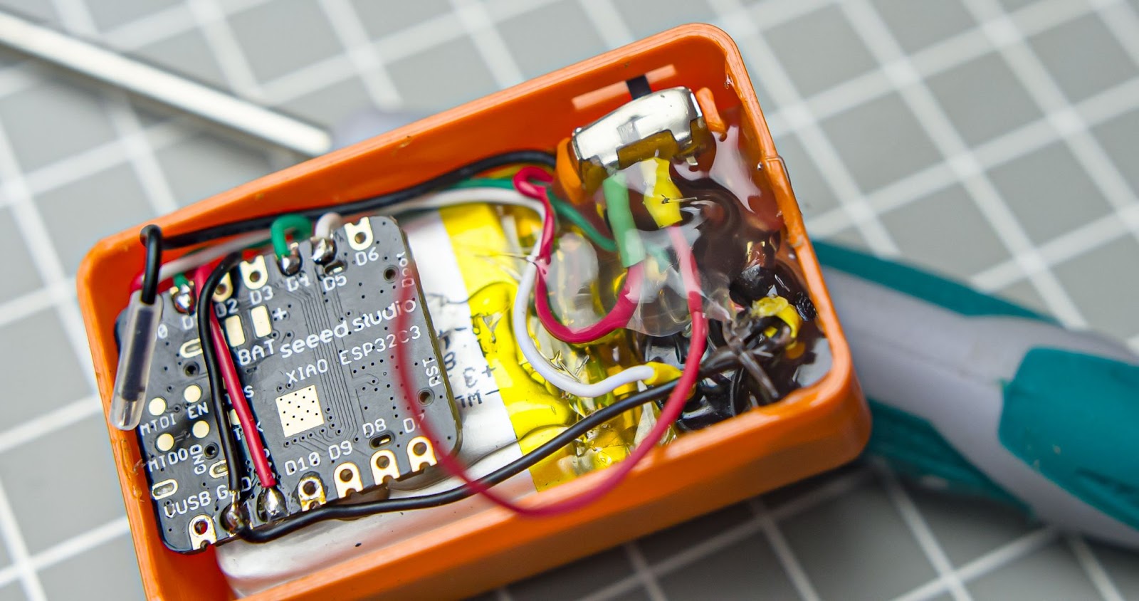
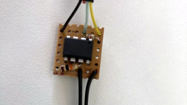
A normal water heater, at least one based on electric resistive heaters, attempts to maintain a small range of temperatures within the insulated tank. If the temperature drops due to use or loss to the environment, the heaters turn on to bring the temperature back up. This automation system does essentially the same thing, but allows a much wider range of temperatures depending on the time of day. Essentially, it allows the water heater to get much hotter during times when solar energy is available, and lets it drop to lower values before running the heater on utility electricity during times when it isn’t. Using a combination ESP32 and ATtiny to both control the heater and report its temperature, all that’s left is to program Home Assistant to get the new system to interact with the solar system’s battery charge state and available incoming solar energy.
While it’s an elegantly simple system that also affords ample hot water for morning showers, large efficiency gains like this can be low-hanging fruit to even more home energy savings than solar alone provides on paper. Effectively the water heater becomes another type of battery in [Rogan]’s home, capable of storing energy at least for the day in the form of hot water. There are a few other ways of storing excess renewable energy as well, although they might require more resources than are typically available at home.