A WiFi RGB Camera Grip Is Probably Not Ideal For Night Shoots

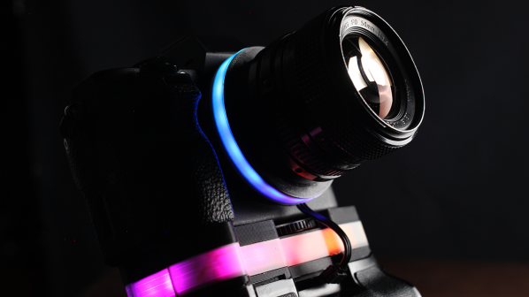
RGB LEDs can be found on everything from motherboards to sticks of RAM these days. [dslrdiy] wanted to bring this same visual flair to his camera setup, so built what he’s calling the world’s first RGB camera grip.

The build is based on an existing off-the-shelf camera grip. It’s disassembled for the build, with a pair of 18650 lithium batteries installed inside as a power supply. They run a small DC-DC converter, which powers a Raspberry Pi Zero and a WS2812B LED strip which provides the lovely colorful lighting effects. The LEDs light up a translucent spacer installed in the camera grip solely for the purpose of aesthetics.

So far, so straightforward. However, [dslrdiy] also implemented one more useful feature. The Pi Zero is able to scrape photos from the camera, and automatically load them on to a Windows network share. That’s a nice zero-fuss way to get pictures off your camera when you return to your home network.

We’re not sure too many professional photographers will rush after the RGB grip, as it’s often poor practice to introduce strange uncontrolled colorful lights into a scene. However, the wireless tethering feature does seem attractive depending on your usual workflow. Video after the break.

Continue reading “A WiFi RGB Camera Grip Is Probably Not Ideal For Night Shoots”

A Nifty Tool For Counting Neopixels

Picture it. You’ve got a big roll of NeoPixels, but you have no idea how many are actually on the tape. Or you need to count how many WS2812B LEDs are in a display to properly plan your animations. Fear not, for [Gustavo Laureano] has built the perfect tool for counting the addressable LEDs.

The tool is based on a Raspberry Pi Pico, so it’s easy to replicate at home. The LED strip is simply connected to the microcontroller via a set of jumper wires going to the 5V and GND pins, while one of the Pico’s ADC pins is then connected to the strip’s GND pin after the jumper. A further GPIO pin is used to send data to the strip.

Essentially, this uses the jumper wire as a rudimentary current shunt. The code steps through the string of LEDs, turning each one on and then off in turn, comparing the value read by the ADC pin at each state. When the Pico detects no difference in current draw between the on and off states, that suggests it’s trying to turn on an LED beyond the end of the string, and thus the count is concluded.

You don’t need to understand any of that to put this device to good use, however. You can easily whip it up on a breadboard with a Pi Pico and parts you have lying around in the shop. Video after the break.

Continue reading “A Nifty Tool For Counting Neopixels”

Building A Digital Compass With An Arduino

The magnetic compass has been a crucial navigational tool for around a thousand years or so, perhaps longer. While classical versions still work perfectly well, you can now get digital magnetometers that work in much the same way. [mircemk] decided to whip up a digital compass to demonstrate the value of these parts.

The build uses a HMC5883L magnetometer. While this can detect magnetic fields in three axes, just one is necessary for building a device that operates akin to a traditional compass. The output of the device is read by an Arduino Nano, which is hooked up to a string of WS2812B LEDs and a small OLED display. The LEDs display the bearing of magnetic north, while the OLED screen shows the current angle between the compass’s arrow and magnetic north.

It’s a tidy build that would be a great educational resource for teaching both electronics and navigational skills. We’ve seen similar projects before, like the hilarious Pizza Compass. Video after the break.

Continue reading “Building A Digital Compass With An Arduino”

Electronic Earrings Are PCB Art You Can Wear

If there’s one area of the human anatomy we rarely try to draw the eye, it’s the ears. Nonetheless, [DIY GUY Chris] has developed some LED earrings that should do exactly that.

The earrings are made using PCBs as the very body of the jewelry itself. The PCBs for each ear play host to eight WS2812 LEDs in a tiny 2020 form factor. The LEDs get their instructions from an ATtiny13-A AVR microcontroller, with some further supporting hardware to get everything playing happily together. Each earring runs off a single CR1220 coin cell, which sits on the obverse side of the earring to stay out of sight. The earrings are programmed with pogo pins to avoid the need for any bulky connectors.

By virtue of the tiny addressable LEDs, the earrings are capable of displaying full RGB colors. [DIY GUY Chris] has programmed the earrings with simple color fades, as well  as some fancier chase animations as well.

We’ve seen some great PCB jewelry before, too. Video after the break.

Continue reading “Electronic Earrings Are PCB Art You Can Wear”

Electronic Connect 4 Console Doesn’t Use LCD

You might think that making your own electronic games would require some kind of LCD, but lately, [Mirko Pavleski] has been making his using inexpensive 8X8 WS2812B LED panels. This lets even a modest microcontroller easily control a 64-pixel “screen.” In this case, [Mirko] uses an Arduino Nano, 3 switches, and a buzzer along with some 3D printed components to make a good-looking game. You can see it in action in the video below.

The WS2812B panels are easy to use since the devices have a simple protocol where you only talk to the first LED. You send pulses to determine each LED’s color. The first LED changes color and then starts repeating what you send to the next LED, which, of course, does the same thing. When you pause a bit, the array decides you are done, and the next train of pulses will start back at the first LED.

It looks like the project is based on a German project from [Bernd Albrecht], but our German isn’t up to snuff, and machine translation always leaves something to be desired. Another developer added a play against the computer mode. This is a simple program and would be easy to port to the microcontroller of your choice. [Mirko]’s execution of it looks like it could be a commercial product. If you made one as a gift, we bet no one would guess you built it yourself.

Of course, you could play a real robot. You could probably repurpose this hardware for many different games, too.

Continue reading “Electronic Connect 4 Console Doesn’t Use LCD”

Bringing The PIO To The FPGA

We’ve seen some pretty incredible hacks using the Raspberry Pi 2040. However, one of the most exciting bits of hardware onboard is the Programmable I/O (PIO). Not content with it just being a part of RP2040-based projects, [Lawrie Griffiths] has been porting the PIO to Verilog so anyone can enjoy it.

This particular implementation is based only on the spec that Raspberry Pi provides. For assembling PIO code, [Lawrie] uses Adafruit’s pioasm assembler they use for their MicroPython framework. There’s a simulator to test different programs, and the project targets the Blackice MX and the Ulx3s. A few example programs are included in the repo, such as outputting a pleasant guitar note over I2S and driving a chain of WS2812s.

The project is still incomplete but slowly making progress. It’s an incredible feat of reverse engineering. While the simulator can be used to debug programs, step through instructions, and inspect waveforms, the ultimate value of bringing the PIO to other systems is that now we can re-use the code. Things like the can2040, an implementation of the CAN bus protocol using the PIO. Or even a PIO-based USB host.

Visual Ear Demonstrates How The Cochlea Works

The cochlea is key to human hearing, and it plays an important role in our understanding of complex frequency content. The Visual Ear project aims to illustrate the cochlear mechanism as an educational tool.

The cochlea itself is the part of the ear that converts the pressure waves of sound into electrical signals for the brain. Different auditory frequencies excite different parts of the cochlea. The cells in the different parts of the cochlea then send signals to the brain corresponding to the sound it has picked up.

The Visual Ear demonstrates similar behavior on a strip of addressable LEDs. Lower LEDs coded in the red part of the color spectrum respond to low frequency audio. Higher LEDs step through yellow, green, and up to blue, and respond to the higher frequencies in turn. This is achieved at a high response rate with the use of a Teensy 4.0 running a Fast Fourier Transform on incoming audio, and then outputting signals to run a string of WS2812B LEDs. The result is a visual band display of 104 bands spanning 43 Hz up to 16,744 Hz, which covers most but not all of the human range of hearing.

It’s an impressive display, and one that makes a great music visualizer, too. When teaching the physics of human hearing and the cochlea, we can imagine such a tool would be quite useful.

Continue reading “Visual Ear Demonstrates How The Cochlea Works”