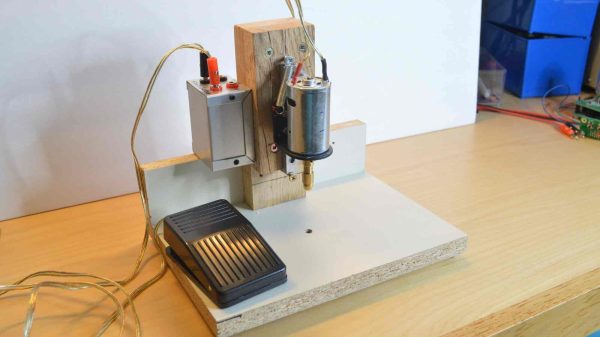
The design isn’t particularly fancy or pretty, but just simply focuses on doing a simple job well. There’s a basic DC motor, sitting on a linear rail so that it has minimal deflection in the X and Y axes as it moves up and down. Special care was taken to ensure the linear rail was mounted perfectly perpendicular to the base to ensure the drill doesn’t wander or splay off target.
A collet chuck is used to center the bit as well as possible for a good price. The build also includes a bright LED in order to give you the best possible view of your work. Power is via a variable bench supply which allows for variable speed as necessary. There’s a foot pedal to activate the drill which allows both hands to be used for positioning the work for added ease of use.
Living and working in a remote rain forest may sound idyllic to those currently stuck in bland suburbia, and to be sure it does have plenty of perks. One of the downsides, though, is getting new materials and equipment to that remote location. For that reason, [Digital Naturalism Laboratories], also known as [Dinalab], has to reuse or recycle as much as they can, including their scraps of acrylic leftover from their laser cutter.
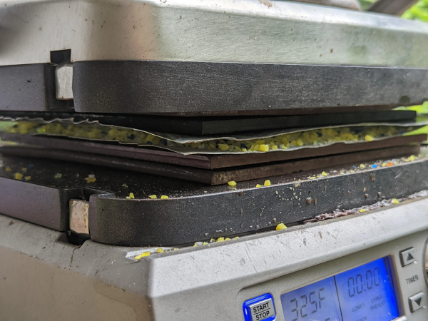
The process might seem straightforward, but getting it to actually work and not burn the acrylic took more than a few tries. Acrylic isn’t as thermoplastic as other plastics so it is much harder to work with, and it took some refining of the process. But once the details were ironed out, essentially the acrylic scraps are gently heated between two steel plates (they use a sandwich press) and then squeezed with a jack until they stick back together in one cohesive sheet. The key to this process is to heat it and press it for a long time, typically a half hour or more.
With this process finally sorted, [Dinalab] can make much more use of their available resources thanks to recycling a material that most of us would end up tossing out. It also helps to keep waste out of the landfill that would otherwise exist in the environment indefinitely. And, if this seems familiar to you, it’s because this same lab has already perfected methods to recycle other types of plastic as well.
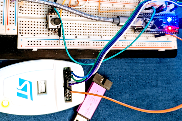
I’ll confess. Although printf-style debugging has a bad rep, I find myself turning to it on occasion. Sure, printf is expensive and brings in a lot of code, but if you have the space and time to use it while debugging you can always remove it before you are finished. However, what if you don’t have an output device or you are using it for something else? If you are using most modern ARM chips, you have another option — a dedicated output channel that is used for several things, including debugging output. I decided I wanted to try that on the Blackpill running mbed, and found out it isn’t as easy as you might think. But it is possible, and when you are done reading, you’ll be able to do it, too.
I’m writing this using the STM32-specific ST-LINK hardware. If you use other JTAG devices like the BlackMagic probe, you probably already have this set up for you.
What You Get
I’ll start backward with the end result, then talk about the software, so you’ll be good and motivated by the time you get to the hardware requirements. Spoiler alert: your existing hardware might need a quick hack to make it work, although you can buy something off the shelf if you prefer.
Here is a very simple test program:
SWO_Channel debugport;  // requires #include "SWO.h"
int main()
  {
  unsigned count=0;
  debugport.printf("\r\nHello World from SWO\r\n");
  debugport.printf("CPU SystemCoreClock is %d Hz\r\n", SystemCoreClock);

  while (1)
    {
    led = !led; // flip LED if output is true
    ThisThread::sleep_for(rate); // sleepy time
    if (count % 10) debugport.putc('*'); else debugport.printf("%d\r\n",count);
    count++;
    }
}
Golf is a sport that has always enjoyed a good gadget or eight. Whether it’s something to measure the wind, or the latest putter guaranteed to save your game, golf enthusiasts have always flocked to such toys. [Nick O’Hara] has something that might just be a little too exciting for the golf set, though, in the form of his golf club launcher.
The golf club launcher essentially takes the role of a normal golf bag, with a rotating magazine containing all the necessary clubs for a day out on the green. The magazine is rotated into position on request, and the required club is launched out towards the player thanks to a pneumatic cylinder fired at 120 psi. A compressor in the base keeps the system charged with air for repeated launches.
The launcher even has a voice assistant built in. Telling the caddy the distance to the hole, and variables like wind and elevation, allows the device to select the right club for the conditions before blasting it towards the player.
The rise of streaming services on the Internet was a revolutionary shift when it came to the world of media. No more would content be pumped in to homes in a one-way fashion, broadcast by major conglomerates and government-run organizations. Instead, individuals would be free to hunt for content suiting their own desires on an all-you-can-watch basis.
It’s led to a paradigm shift in the way we consume media. However, it’s also led to immense frustration thanks to the overwhelming amount of content on offer. Let’s take a look at why that is, and some creative ways you can get around the problem.
The Paradox of Choice
Many find the masses of content on streaming services to be overwhelming to choose from. Credit: author screenshot
Traditionally, when it came to media, there were two major arms of delivery: broadcast, and home media. One might listen to the radio, or flick on the TV, or alternatively, spin up a record, or select a movie to watch on tape. If none of those options sufficed, one might take a walk down to the local video store to rent something more appealing.
Fundamentally, it was an era in which choices were limited. There were a handful of TV stations to choose from, and if nothing good was on, you could go as far as finding something watchable on tape or going without. Many will remember afternoons and evenings spent watching reruns or a Friday night movie that had been on a million times before. Some shows went as far as becoming legends for their seemingly endless replay, from The Simpsons to M*A*S*H.
As the Internet grew, though, the game started to change. Torrent websites and streaming services came along, offering up the sum total of the world’s cultural output for free, or for a nominal cost for those averse to piracy. Suddenly when it came to choosing a movie to watch, one wasn’t limited to the five or so films on at the local cinema, nor what was left on the shelves at the local video rental. Instead, virtually any movie, from the invention of the format, could be yours to watch at a moment’s notice.
With so many options on the table, many of us find it harder to choose. It’s an idea popularly known as the Paradox of Choice, a term popularized by US psychologist Barry Schwartz in 2004. When our options are limited to a select few, choice is easy. They can quickly be compared and ranked and an ideal option chosen.
Add thousands of choices to the pile, and the job escalates in complexity to the point of becoming overwhelming. With so many different choices to contrast and compare, finding the mythical right choice becomes practically impossible. Continue reading “The Joy Of Broadcast Media Vs. The Paradox Of Choice”→
When one mulls the possibility of detecting pulsars, to the degree that one does, thoughts turn to large dish antennas and rack upon rack of sensitive receivers, filters, and digital signal processors. But there’s more than one way to catch the regular radio bursts from these celestial beacons, and if you know what you’re doing, a small satellite dish and an RTL-SDR dongle will suffice.
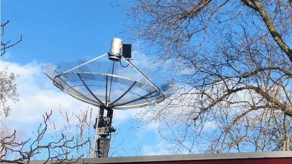
Granted, [Job Geheniau] has had a lot of experience exploring the radio universe. His website has a long list of observations and accomplishments achieved using his “JRT”, or “Job’s Radio Telescope.” The instrument looks like a homebrewer’s dream, with a 1.9-m satellite TV dish and precision azimuth-elevation rotator. Behind the feedhorn are a pair of low-noise amplifiers and bandpass filters to massage the 1,420 MHz signal that’s commonly used for radio astronomy, plus a Nooelec Smart SDR dongle and an Airspy Mini. Everything is run via remote control, as the interference is much lower with the antenna situated at his family’s farm, 50 km distant from his home in The Hague.
As for the pulsar, bloodlessly named PSR B0329+54, it’s a 5-million-year-old neutron star located in the constellation of Camelopardalis, about 3,500 light-years away. It’s a well-characterized pulsar and pulses at a regular 0.71452 seconds, but it’s generally observed with much, much larger antennas. [Job]’s write-up of the observation contains a lot of detail on the methods and software he used, and while the data is far from clear to the casual observer, it sure seems like he bagged it.
We’ve seen quite a few DIY radio astronomy projects before, both large and small, but this one really impresses with what it accomplished.
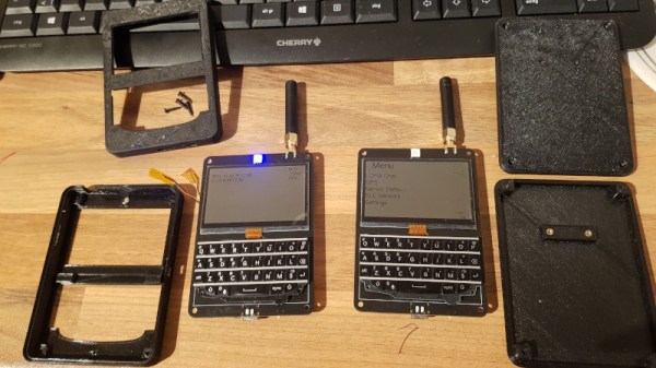
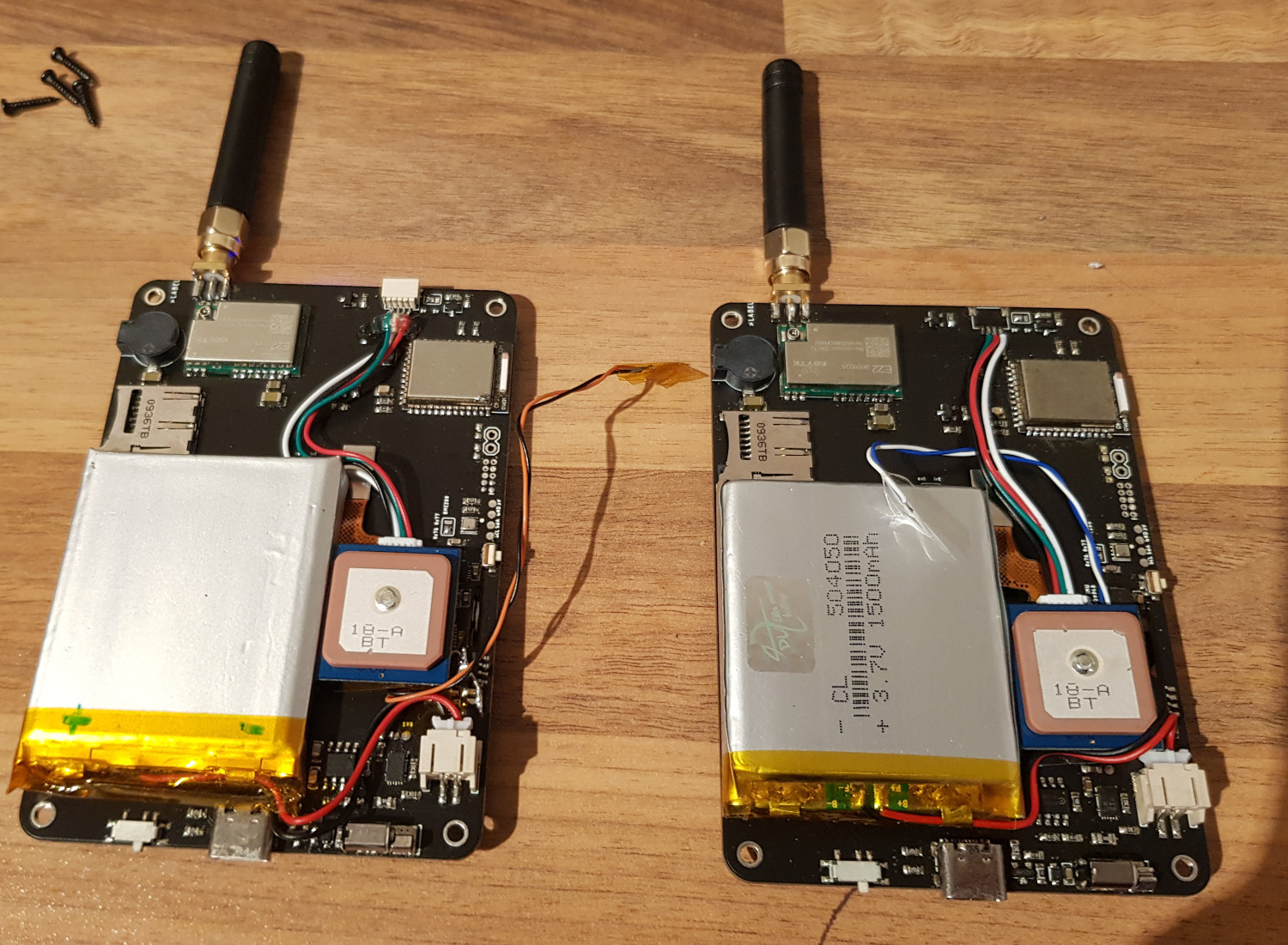
Affordable and reliable cell phones have revolutionized the way we communicate over the last two decades or so, and this change was only accelerated by the adoption of the smartphone. This is all well and good if you’re living in a place with cellular infrastructure, but if you’re in more remote areas you’ll have to be a little more inventive. This text-based communications device, for example, lets you send text messages without all of that cumbersome infrastructure.
While [Arthur] didn’t create this project specifically for off-grid use, it’s an interesting project nonetheless. The devices use a physical QWERTY keyboard and a small screen, reminiscent of BlackBerry devices from the late 2000s (partially because they are actually using BlackBerry keyboards). One of the other goals for this project was low power consumption, and between polling the keyboard, the memory LCDs, and receiving and transmitting messages using LoRa, [Arthur] was able to get the current draw down to 12 mA.
Between the relatively common nRF52840 and SX1262 chips, plus the fact that [Arthur] made the schematics available, this makes for an excellent off-grid device for anyone who likes to drive off into the wilderness or lives far enough outside of town that cell phone reception is a concern.