There was a time following the Second World War when TV sets for the nascent broadcast medium were still very expensive, but there was an ample supply of war-surplus electronic parts including ex-radar CRTs. Thus it wasn’t uncommon at all for electronics enthusiasts of the day to build their own TV set, and magazines would publish designs to enable them. With a burgeoning consumer electronics industry the price of a new TV quickly dropped to the point of affordability so nobody would consider building one themselves today. Perhaps that should be amended to almost nobody, because [Retro Tech or Die] has assembled a small black-and-white CRT TV from a kit he found on AliExpress.
We have to admit to having seen the same kit and despite a sincere love for analogue telly, to have balked at the price. It’s an exceptionally cheap set of the type that was available from discount stores for a laughably low price around the final few years of mainstream analogue TV broadcasting, and having a couple in the stable we can confirm that the value here lies in building the thing rather than owning it.
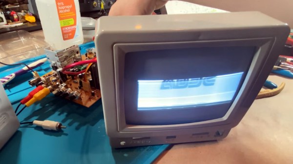
The unboxing and building proceeds as you might expect, with the addition of very poor documentation and extremely low-quality parts. Satisfyingly it works on first power-up, though some adjustment and the reversing of a deflection yoke connection is required for a stable picture. The scanned area doesn’t fill the screen and he doesn’t find the solution in the video, we hope that by his next video someone will have suggested moving the deflection yoke forwards.
Perhaps merely assembling a kit might not seem the most exciting subject for a Hackaday story, but this one is a little different here in 2022. CRT TV sets are now a long-gone anachronism, so for a younger generation there is very little chance to see them up close and thus watching one built has some value. If you want to spend the cash and build your own he’s dropped the link in the YouTube description, otherwise watch the progress in the video below the break.
Fancy learning a bit more about analogue TV? Have a dive into the video waveform. Or for a bit more CRT goodness, learn about converging a delta-gun colour set from the days when a TV weighed almost as much as you did.
Continue reading “Build Your Own CRT TV” →