A badge modelled after the handle of a light sabre? Yes Please! This Star Wars themed hardware is the work of hardware designer Thomas Flummer for the 2019 BornHack conference held in Denmark last month. (Check out my roundup of the event if this is the first you’ve heard of it.)
It’s not a badge but a light sabre! The front of the BornHack 2019 badge.
It fits the hand nicely, and with clever side-on placement of the two AA battery holders (a trick we first saw with the 2016 Hackday Superconference badge) it also keeps any protruding solder joints away from clothing. In the centre of the badge is the 240×240 pixel colour display that also hides the Silicon Labs Happy Gecko processor and its surrounding components. Three buttons at the edge of the board to the left of the screen are a nice fit for your thumb when holding it in your left hand — a good choice if you happen to leave your right hand behind on a visit to the Cloud City of Bespin.
Between the battery holders lies a four-way joystick, two buttons, and a 6-pin add-on connector. Above it is a micro SD card socket and a micro USB socket, and above them are an IR emitter and receiver. All of the hardware is on the front of the PCB, with no components on the reverse (other than the solder joints for the batteries). But it is there you will find a set of exposed pads for serial and I2C interfaces. Continue reading “Hands-On: BornHack’s Light Sabre Badge”→
Hackaday Editors Mike Szczys and Elliot Williams get caught up on the most interesting hacks of the past week. On this episode we take a deep dive into radiation-monitor projects, both Geiger tube and scintillator based, as well as LED cube projects that pack pixels onto six PCBs with parts counts reaching into the tens of thousands. In the 3D printing world we want non-planar printing to be the next big thing. Padauk microcontrollers are small, cheap, and do things in really interesting ways if you don’t mind embracing the ecosystem. And what’s the best way to read a water meter with a microcontroller?
Take a look at the links below if you want to follow along, and as always tell us what you think about this episode in the comments!
Take a look at the links below if you want to follow along, and as always, tell us what you think about this episode in the comments!
If you’re enjoying a Western Canadian summer, two of the best ways to do so involve a hammock, or a boat. Seeking to improve on this mighty duo with a hammock-boat combo, [Jarrett] describes his progress at Vancouver Hack Space.
The boat he chose was a one-person catamaran with an aluminium frame and what appear to be inflatable pontoons, while the hammock is one designed for a garden or patio with a steel tubular frame. A design goal was to not modify or destroy the structure of either item, so the challenge was to securely mount the two frames together. A variety of false starts involving bent steel or aluminium were tried, followed by a final success with the aluminium tubes reinforced with more tube inside them, and the hammock attached with U-bolts.
The testing took place on what appears to be a public lake, and the contraption floated well. When it had been pushed out to a landing stage our intrepid adventurer boarded the hammock — and promptly the whole edifice tipped itself over, depositing him in the drink. Further experimentation revealed that balance was critical, and a revised position could achieve a stable boarding. He paddles off into the sunset as you can see in the video below the break, though as his friends remind him, without his beer.
Commercial hammocks are surprisingly expensive for what they are. Don’t worry though, if you find them to be beyond your budget you can always make a frame for one yourself.
We often think of SIM cards as simple data storage devices, but in reality a SIM card is a miniature Universal integrated circuit card, or smart card. Subscriber data isn’t a simple text string, but a program running on the smart cards tiny processor, acting as a hardware cryptographic token. The presence of this tiny processor in everyone’s cell phone was eventually put to use in the form of the Sim application ToolKit (STK), which allowed cell phone networks to add services to very basic cell phones, such as mobile banking and account management.
Legacy software running in a place most of us have forgotten about? Sounds like it’s ripe for exploitation. The researchers at Adaptive Mobile Security discovered that exploitation of SMS messages has been happening for quite some time. In an era of complicated and sophisticated attacks, Simjacker seems almost refreshingly simple. An execution environment included on many sim cards, the S@T Browser, can request data from the cell phone’s OS, and even send SMS messages. The attacker simply sends an SMS to this environment containing instructions to request the phones unique identifier and current GPS location, and send that information back in another SMS message.
What’s in your crypto wallet? The simple answer should be fat stacks of Bitcoin or Ethereum and little more. But if you use a hardware cryptocurrency wallet, you may be carrying around a bit fat vulnerability, too.
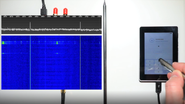
At the 35C3 conference last year, [Thomas Roth], [Josh Datko], and [Dmitry Nedospasov] presented a side-channel attack on a hardware crypto wallet. The wallet in question is a Ledger Blue, a smartphone-sized device which seems to be discontinued by the manufacturer but is still available in the secondary market. The wallet sports a touch-screen interface for managing your crypto empire, and therein lies the weakness that these researchers exploited.
By using a HackRF SDR and a simple whip antenna, they found that the wallet radiated a distinctive and relatively strong signal at 169 MHz every time a virtual key was pressed to enter a PIN. Each burst started with a distinctive 11-bit data pattern; with the help of a logic analyzer, they determined that each packet contained the location of the key icon on the screen.
Next step: put together a training set. They rigged up a simple automatic button-masher using a servo and some 3D-printed parts, and captured signals from the SDR for 100 presses of each key. The raw data was massaged a bit to prepare it for TensorFlow, and the trained network proved accurate enough to give any hardware wallet user pause – especially since they captured the data from two meters away with relatively simple and concealable gear.
Every lock contains the information needed to defeat it, requiring only a motivated attacker with the right tools and knowledge. We’ve covered other side-channel attacks before; sadly, they’ll probably only get easier as technologies like SDR and machine learning rapidly advance.
We’re going to go out on a limb here and say that the controller for Steel Battalion on the original Xbox is the most impressive video game peripheral ever made. Designed to make players feel like they were really in the cockpit of a “Vertical Tank”, the controller features dual control sticks, three pedals, a gear selector, and dozens of buttons, switches, and knobs. Unfortunately, outside of playing Steel Battalion and its sequel, there’s not a whole lot you can do with the monstrous control deck.
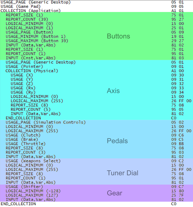
HID Report Descriptor
But now, nearly 20 years after the game released, [Oscar Sebio Cajaraville] has not only developed an open source driver that will allow you to use the infamous mech controller on a modern Windows machine, but he’s part of the team developing a new game that can actually be played with it. Though gamers who are imagining piloting a futuristic combat robot in glorious 4K might be somewhat disappointed to find that this time around, the Steel Battalion controller is being used to operate a piece of construction equipment.
In his blog post, [Oscar] focuses on what it took to develop a modern Windows driver for a decades old controller. It helps that the original Xbox used what was essentially just a rewiring of USB 1.0 for its controllers, so connecting it up didn’t require any special hardware. Unfortunately, while the controller used USB to communicate with the console, it was not USB-HID compliant.
As it turns out, Microsoft actually provides an open source example driver that’s specifically designed to adapt non-HID USB devices into a proper game controller the system will recognize. This gave [Oscar] a perfect starting point, but he still needed to explore the controller’s endpoints and decode the data it was sending over the wire. This involved creating a HID Report Descriptor for the controller, a neat trick to file away mentally if you’ve ever got to talk to an oddball USB device.
Earlier this year we saw an incredible simulator built around the Steel Battalion controller, were an external “coach” could watch you play and give you tips on surviving the virtual battlefield. But even that project still used the original game; hopefully an open source driver that will get this peripheral working on Microsoft’s latest OS will help spur the development of even more impressive hacks.
For many of us, ad hoc projects end up having a certain permanence to them. Think of the number of Raspberry Pis and RTL-SDRs that are just dangling from a USB cable under a desk or stuffed behind a monitor, quietly going about their business. If it ain’t broke, don’t fix it.
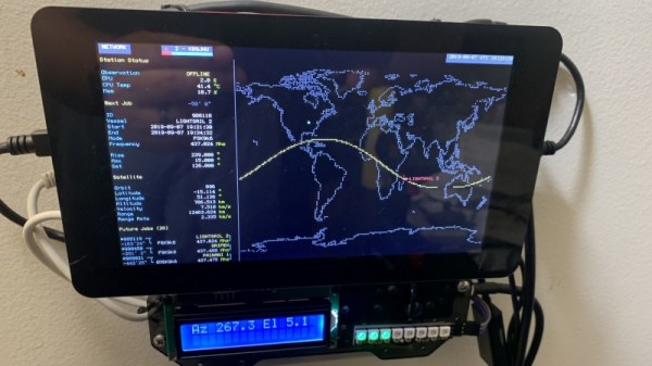
Some projects, though, just end up accreting past the acceptable point. This wall-mounted SatNOGS ground station is a great example of what happens when something needs to be done about the mess. The pile of stuff that [cshields] had cobbled together over time for his ground station needed tidying, so he laid hands on a new Pi 4 and a cool enclosure/breadboard called a Stegoboard. This is just a piece of acrylic with a variety of holes laid out to match every imaginable PC board, hard drive, PC motherboard, Arduino, and just about anything out there that needs mounting. To contain the mess, he mounted the Pi and a 7″ touchscreen to the Stegoboard, along with an RTL-SDR and an Arduino to control his antenna rotator. The ground station wiring is still a little rough, but worlds better than what it was, and now that it’s mounted on the wall it’ll be much easier to use.
For those not familiar with SatNOGS, check out our article back from when the Satellite Network of Ground Stations won the 2014 Hackaday Prize. In the half-decade since then, SatNOGS has only grown, with a huge following of dedicated enthusiasts pointing their antennas at the sky. We know how to pick ’em, and we’ll be selecting the 2019 Hackaday Prize winner very soon.