Sometimes you have this project idea in your mind that seems so simple and straightforward, and which feels just so right that you have to roll with it. Then, years later you stumble across the sad remnants of the tearful saga and the dismal failure that it portrays. Do you put it away again, like an unpleasant memory, or write it up in an article, as a tearful confession of past sins? After some coaxing by a friend, [Alessandro] worked up the courage to detail how he set about making a hardware-only password keeper, and why it failed.
The idea was so simple: the device would pretend to be a keyboard and type the passwords for you. This is not that unusual, as hardware devices like the Mooltipass do something similar. Even better, it’d be constructed only out of parts lying around, including an ATtiny85 and an HD44780 display, with bit-banged USB connectivity.
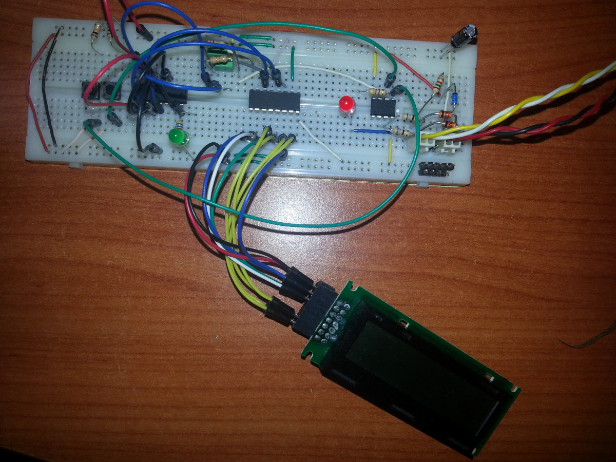
Overcoming the challenge of driving the LC display with one pin on the MCU required adding a 74HC595 demultiplexer and careful timing, which sort of worked when the stars aligned just right. Good enough, but what about adding new passwords?
This is where things quickly skidded off the tracks in the most slapstick way possible, as [Alessandro] solved the problem of USB keyboard HID devices being technically ‘output-only’, by abusing the indicator statuses for Caps Lock, Num Lock, and Scroll Lock. By driving these from the host PC in just the right way you can use them as a sort of serial protocol. This incidentally turned out to be the most reliable part of the project.
Where the project finally tripped and fell down the proverbial flight of stairs was when it came to making the bit-banged USB work reliably. As it turns out, USB is very unforgiving with its timing unlike PS/2, making for an infuriating user experience. After tossing the prototype hardware into a box, this is where the project gathered dust for the past years.
If you want to give it a try yourself, maybe using an MCU that has more GPIO and perhaps even a USB hardware peripheral like the STM32F103, ESP32-S3 or something fruit-flavored, you can take a gander at the project files in the GitHub repository.
We’re always happy to see projects that (ab)use the Lock status indicators, it’s always been one of our favorite keyboard hacks.