A combination of cheap USB HID capable microcontrollers, the ability to buy individual mechanical keys online, and 3D printing has opened up a whole new world of purpose-built input devices. Occasionally these take the form of full keyboards, but more often than not they are small boards with six or so keys that are dedicated to specific tasks or occasionally a particular game or program. An easy and cheap project with tangible benefits to anyone who spends a decent amount of time sitting in front of the computer certainly sounds like a win to us.
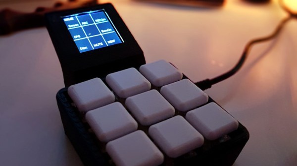
 But this build by [r0ckR2] takes the concept one step farther. Rather than just being a simple 3×3 keypad, his includes a small screen that shows the current assignments for each key. Not only does this look really cool on the desk (always important), but it also allows assigning multiple functions to each key. The screen enables the user to switch between different pages of key assignments, potentially allowing a different set of hot keys or macros for every piece of software they use.
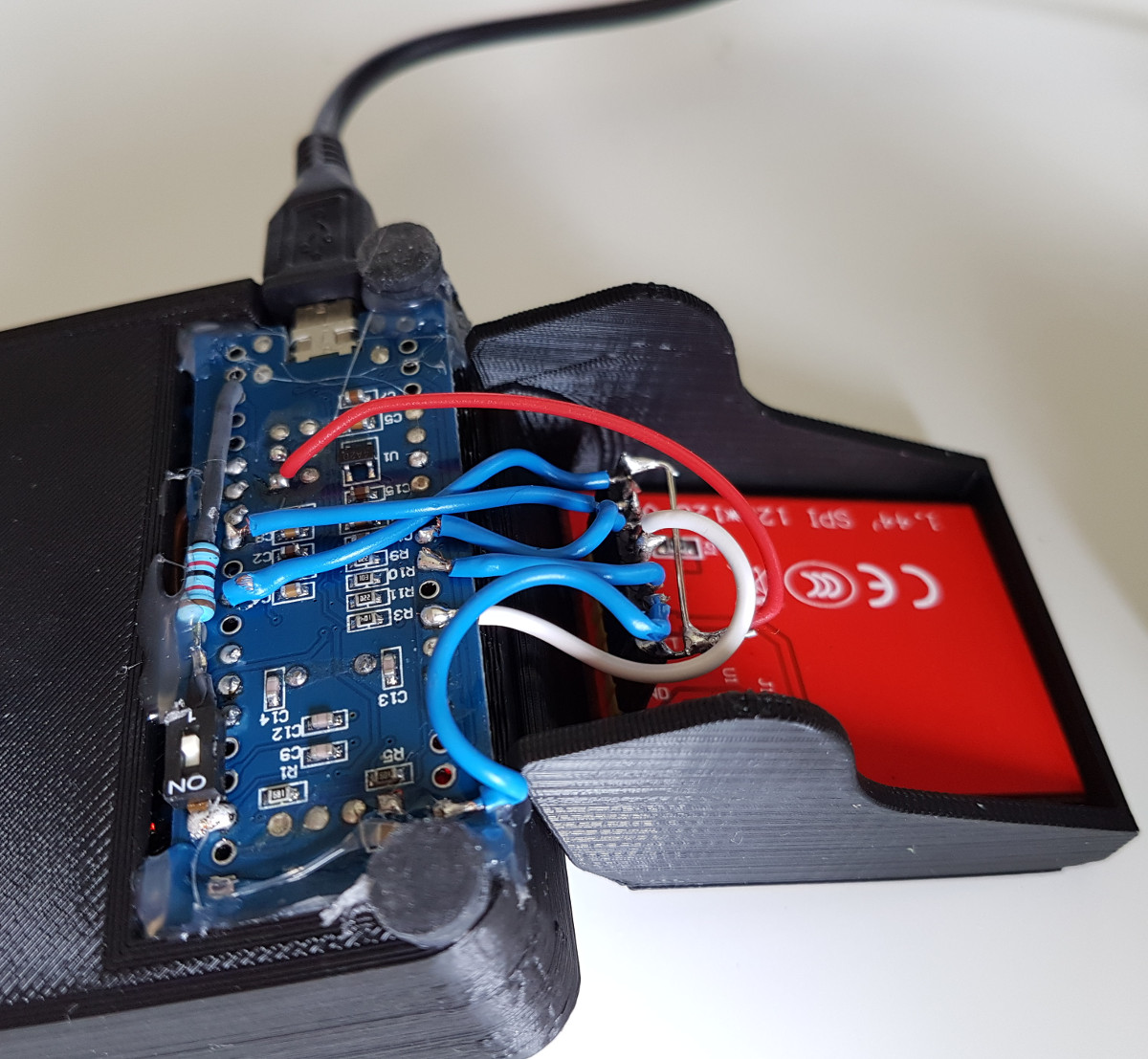
The case is entirely 3D printed, as are the key caps. To keep things simple, [r0ckR2] didn’t bother to design a full enclosure, leaving all the electronics exposed on the back. Some might think it’s a little messy, but we appreciate the fact that it gives you easy access to the internals if you need to fix anything. Rubber feet were added to the bottom so it doesn’t slide around while in use, but otherwise the case is a pretty straightforward affair.
As for the electronics, [r0ckR2] went with an STM32 “Blue Pill” board, simply because it’s what he had on hand. The screen is a ST7735 1.44 inch SPI TFT, and the keys themselves are Cherry MX Red clones he got off of eBay. All in all, most of the gear came from his parts bins or else was only a couple bucks online.
If you’re looking for something a bit bigger, check out this gorgeous Arduino-powered version, or this far more utilitarian version. Both are almost entirely 3D printed, proving the technology is capable of more than making little boats.
[via /r/functionalprint]