Perhaps the most important consideration to make when designing a battery-operated device of any kind is the power consumption. Keeping it running for longer between battery changes is often a key design point. To that end, if you need to know how small programming changes will impact the power consumption of your device then [Daniel] has a great tool that you might find helpful: an ESP8266-based live power meter.
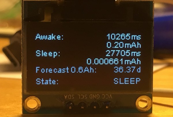
The power meter itself is battery-powered via a 600 mAh battery and monitors an e-paper module, which also displays information about power consumption. It runs using a NodeMCU and measures voltage and current across a 100-ohm resistor to calculate the power use, although the resolution does start to get noisy when the device is in standby/sleep mode. One presumes this could be solved by changing the value of the resistor in order to get more accurate measurements at the expense of losing accuracy during moments of high power consumption.
While this power monitor was built specifically to monitor power consumption on this particular e-paper display project, it should be easily portable into other battery-based systems that need fine tuning in order to maximize battery life. As a bonus, the display is already included in the project. There are ways of getting even more information about your battery usage, although if power consumption is important than you may want to stick with a more straightforward tool like this one.