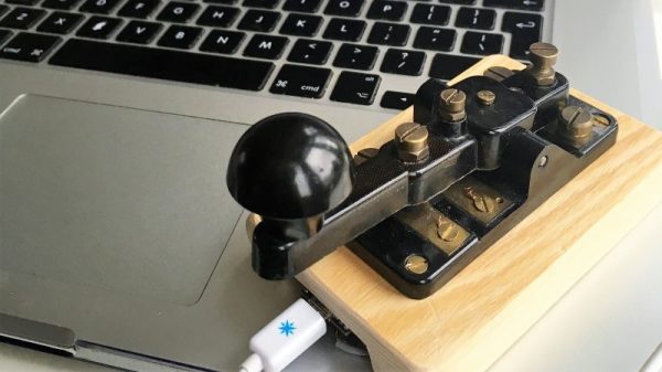
The Arduino Foundation: What’s Up?

The Arduino Wars officially ended last October, and the new Arduino-manufacturing company was registered in January 2017.  At the time, we were promised an Arduino Foundation that would care for the open-source IDE and code infrastructure in an open and community-serving manner, but we don’t have one yet. Is it conspiracy? Or foul play? Our advice: don’t fret. These things take time.

But on the other hand, the Arduino community wants to know what’s going on, and there’s apparently some real confusion out there about the state of play in Arduino-land, so we interviewed the principals, Massimo Banzi and Federico Musto, and asked them for a progress report.

The short version is that there are still two “Arduinos”: Arduino AG, a for-profit corporation, and the soon-to-be Arduino Foundation, a non-profit in charge of guiding and funding software and IDE development. The former was incorporated in January 2017, and the latter is still in progress but looks likely to incorporate before the summer is over.

Banzi, who is a shareholder of Arduino AG, is going to be the president of the Foundation, and Musto, AG’s CEO, is going to be on the executive board and both principals told us similar visions of incredible transparency and community-driven development. Banzi is, in fact, looking to get a draft version of the Foundation’s charter early, for comment by the community, before it gets chiseled in stone.

It’s far too early to tell just how independent the Foundation is going to be, or should be, of the company that sells the boards under the same name. Setting up the Foundation correctly is extremely important for the future of Arduino, and Banzi said to us in an interview that he wouldn’t take on the job of president unless it is done right. What the Arduino community doesn’t need right now is a Foundation fork.  Instead, they need our help, encouragement, and participation once the Foundation is established. Things look like they’re on track.

Continue reading “The Arduino Foundation: What’s Up?”

Intel Discontinues Joule, Galileo, And Edison Product Lines

Sometimes the end of a product’s production run is surrounded by publicity, a mix of a party atmosphere celebrating its impact either good or bad, and perhaps a tinge of regret at its passing. Think of the last rear-engined Volkswagens rolling off their South American production lines for an example.

Then again, there are the products that die with a whimper, their passing marked only by a barely visible press release in an obscure corner of the Internet. Such as this week’s discontinuances from Intel, in a series of PDFs lodged on a document management server announcing the end of their Galileo (PDF), Joule (PDF), and Edison (PDF) lines. The documents in turn set out a timetable for each of the boards, for now they are still available but the last will have shipped by the end of 2017.

It’s important to remember that this does not mark the end of the semiconductor giant’s forray into the world of IoT development boards, there is no announcement of the demise of their Curie chip, as found in the Arduino 101. But it does mark an ignominious end to their efforts over the past few years in bringing the full power of their x86 platforms to this particular market, the Curie is an extremely limited device in comparison to those being discontinued.

Will the departure of these products affect our community, other than those who have already invested in them? It’s true to say that they haven’t made the impression Intel might have hoped, over the years only a sprinkling of projects featuring them have come our way compared to the flood featuring an Arduino or a Raspberry Pi. They do seem to have found a niche though where there is a necessity for raw computing power rather than a simple microcontroller, so perhaps some of the legion of similarly powerful ARM boards will plug that gap.

So where did Intel get it wrong, how did what were on the face of it such promising products fizzle out in such a disappointing manner? Was the software support not up to scratch, were they too difficult to code for, or were they simply not competitively priced in a world of dirt-cheap boards from China? As always, the comments are open.

Header image: Mwilde2 [CC BY-SA 4.0].

Better LEDs Through DMA

While regular Hackaday readers already know how to blink a LED with a microcontroller and have moved onto slightly more challenging projects such as solving the Navier-Stokes equations in 6502 assembly, that doesn’t mean there’s not space for newbies. [Rik] has published a great tutorial on abusing DMA for blinkier glowy things. Why would anyone want to learn about DMA techniques? For blinkier glowy things, of course.

This tutorial assumes knowledge of LED multiplexing and LED matrices, or basically a bunch of LEDs connected together on an XY grid. The naive way to drive an 8×8 grid of LEDs is attaching eight cathodes to GPIO pins on a microcontroller, attaching the eight anodes to another set of GPIO pins, and sourcing and sinking current as required. The pin count can be reduced with shift registers, and LED dimming can be implemented with PWM. This concludes our intensive eight-week Arduino course.

Thanks to microcontrollers that aren’t trapped in the 1980s, new techniques can be used to drive these LED matrices. Most of the more powerful ARM microcontrollers come with DMA, a peripheral for direct memory access. Instead of having the CPU do all the work, the DMA controller can simply shuffle around bits between memory and pins. This means blinker projects and glowier LEDs.

[Rik]’s method for DMAing LEDs includes setting up a big ‘ol array in the code, correctly initializing the DMA peripheral, and wiring up the LED matrix to a few of the pins. This technique can be expanded to animations with 64 levels of brightness, something that would take an incredible amount of processing power (for a microcontroller, at least) if it weren’t for the DMA controller.

The setup used in these experiments is an STM32F103 Nucleo board along with the OpenSTM32 IDE. [Rik] has released all the code over on GitHub, and you are, of course, encouraged to play around.

Voice Shifting With A Cyclone V FPGA

Cornell Students [Sean Carroll], [Gulnar Mirza], and [James Talmage] designed a realtime pitch shifter to run on their DE1-SoC and controlled by its ARM core.

The team’s goals were to pitch-shift the left and right outputs independently, to produce chords using the original voices as well as the pitch-shifted ones, and time-delayed pitch shifting. All of it is controlled on a VGA monitor through a simple GUI, allowing users to create lots of different effects by layering the different options.

Under the hood they made use of dual circular buffers to do the pitch shifting, reading in the sample and then using simple fixed-point arithmetic to modify it, then running the signal through a Butterworth filter to clean up artifacts.

The project was built as part of [Bruce Land]’s ECE5760 class. If you’re looking for more DE1 goodness, you’ll find excellent projects aplenty on Hackaday, including the LED Matrix Audio Visualizer from last year and Synthesizing Strings on a Cyclone V, among many others.

Continue reading “Voice Shifting With A Cyclone V FPGA”

Btrfs For The Pi

File systems are one of those things that typical end users don’t think much about. Apparently, [seaQueue] isn’t a typical end user. He’s posted some instructions on how to run an alternate file system–btrfs–on the Raspberry Pi.

The right file system can make a big difference when it comes to performance and maintainability of any system that deals with storage. Linux, including most OSs for the Raspberry Pi, uses one of the EXT file systems. These are battle-hardened and well understood. However, there are other file systems, many of which have advanced features superior to the default file system for some applications.

Btrfs, often pronounced “butter eff ess”, begin life at Oracle and was born from an idea in an IBM paper. It offers advanced features like pooling, snapshots, and the ability to fuse multiple devices into one logical device. One notable feature the file system offers is copy-on-write. That means file copies can share common blocks as long as they stay common.  Compression is available, as is seeding a file system with read-only storage, which could be very useful in some embedded systems. You can also configure several types of RAID using nothing but btrfs. You can see a video presentation about features of btrfs below.

Continue reading “Btrfs For The Pi”

Hackaday Prize Entry: Very, Very Powerful Servos

A few years ago, [patchartrand] decided to build a robot arm. The specs were simple: he needed a drive system that would be at least as strong as a human arm. After looking at motors, couldn’t find a solution for under $3,000. This led to the creation of the Ultra Servo, an embiggened version of the standard hobby servo that provides more than ten thousand oz-in of torque.

Your typical hobby servo has three main components. The electronics board reads some sort of signal to control a motor. This motor is strapped into a gear train of some sort, and a potentiometer reads the absolute position of a shaft. This is basically what the Ultra Servo is doing, although everything is much, much bigger.

The motor used in the Ultra Servo is a very large brushed DC motor. This is attached to a 160:1 planetary gearbox and the electronics are built around four reasonably large MOSFETs. The electronics are built around the ATmega168 microcontroller, and the specs for the completed servo include 12 V or 24 V operation, TTL, SPI, and standard RC communication, 60 RPM no load speed, and 60 ft-lbs of torque.

This is not your standard servo. This is a massive chunk of metal to move stuff. If you’ve ever wanted a remote-controlled Cessna, here you go. That said, servos of this size and power will always be pricey, and is looking at a cost of $750 per unit. Still, that’s much less than the thousands of a comparable unit, and a great entry to the Hackaday Prize.

Mixed Mode Bench PSU Delivers High Performance

If you have an electronics bench, it follows that you will need some form of bench power supply. While many make do with fixed-voltage supplies it’s safe to say that the most useful bench power supplies have variable voltage and a variable current limiter. These are available in a range of sizes and qualities, and can be had from the usual online suppliers starting with a surprisingly small outlay.

There is however a problem with inexpensive bench power supplies. They are invariably switch-mode designs, and their output will often be noisy. Expensive linear supplies provide a much more noise-free output, but do so at the expense of excessive heat loss when regulating a high voltage drop.

One solution is a mixed-mode design, in which a switch-mode supply does the hard work of reducing the voltage most of the way, and a linear regulator drops the last couple of volts to provide a noise-free output. [Andrei] shows us his design for just such a mixed-mode supply, and it’s one you can have a go at building yourself.

His primary supply is an off-the-shelf switcher that turns mains AC into 24 V DC. This then feeds an LTC1624 buck converter that brings the voltage down to about 1.2 V above the final output voltage, this is in turn fed to a parallel pair of LT3081 linear regulators that deliver the final noise-free output. There is an INA260 for voltage and current measurement, and an Arduino with LCD display as a user interface. His prototype has been nicely constructed using a four-layer PCB, though he suggests it could be made on stripboard with the appropriate SMD adaptors. The cardboard chassis he’s used looks slightly alarming though.

We’ve covered numerous bench power supplies here over the years here at Hackaday. If it is an author’s favourite you are seeking though, take a look at the 723.