July 20th, 1969 was the day that people from Earth set foot on different soil for the first time. Here we are 48 years later, and the world’s space programs are — well — not very close to returning to the moon. If you aren’t old enough to remember, it was really amazing. The world was in a lot of turmoil in the 1960s (and still is, of course) but everyone stopped to look at the sky and listen to the sound of [Neil Armstrong] taking that first step. It was shocking in a good way and almost universally observed. Practically everyone in the world was focused on that one event. You can see some of that in the NASA video, below.
Space flight was an incredible accomplishment, but it paled in comparison with the push to actually landing a person on the moon and bringing them home safely. The effort is a credit to the ability of people to work together (on the order of thousands of minds) to overcome a difficult challenge. We can learn a lot from that alone, and it makes a compelling argument to continue taking on tough problems. Today, as we remember the Apollo landings, let’s take a moment to recognize what came of it beyond an iconic boot-print in the floury lunar soil.
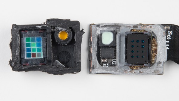
Some of you may remember the SCiO, originally a Kickstarter darling back in 2014 that promised people a pocket-sized micro spectrometer. It was claimed to be able to scan and determine the composition of everything from fruits and produce to your own body. The road from successful crowdsourcing to production was uncertain and never free from skepticism regarding the promised capabilities, but the folks at [Sparkfun] obtained a unit and promptly decided to tear it down to see what was inside, and share what they found.
The main feature inside the SCiO is the optical sensor, which consists of a custom-made NIR spectrometer. By analyzing the different wavelengths that reflect off an object, the unit can make judgments about what the object is made of. The SCiO was clearly never built to be disassembled, but [Sparkfun] pulls everything apart and provides some interesting photos of a custom-made optical unit with an array of different sensors, various filters, apertures, and a microlens array.
It’s pretty interesting to see inside the SCiO’s hardware, which unfortunately required destructive disassembly of the unit in question. The basic concept of portable spectroscopy is solid, as shown by projects such as the Farmcorder which is intended to measure plant health, and the DIY USB spectrometer which uses a webcam as the sensor.
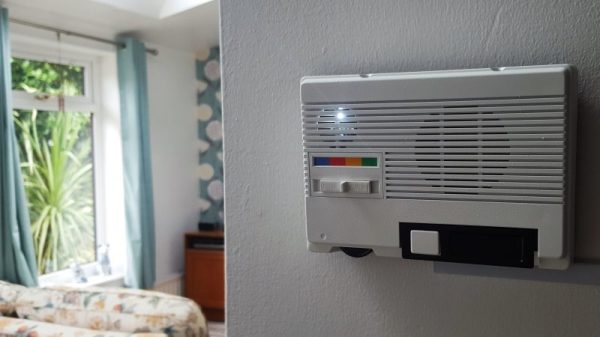
Old Radio Shack intercom; brand new Google Voice interface for a Raspberry Pi. One of these things is not like the other, but they ended up together in this retro-look Google Voice interface, and the results are pretty slick.
The recipient of the Google hive-mind transplant was one of three wireless FM intercoms [MisterM] scored for a measly £4. Looking much as they did when they were the must-have office tool or home accessory for your modern mid-80s lifestyle, the intercom case was the perfect host for the Pi and the Google AIY hat. Only the case was used — not even the original speaker made it into the finished product. The case got a good scrubbing, a fresh coat of paint to perk up the gone-green plastic, and an accent strip of Google’s logo colors over the now-deprecated station selector switch. [MisterM] provided a white LED behind the speaker grille for subtle feedback. A tap of the original talk bar gets Google’s attention for answers to quick questions, and integration into the family’s existing home automation platform turns the lights on and off. See it in action after the break.
[MisterM] was lucky enough to score an AIY hat for free, and as far as we know they’re still hard to come by. If you’re itching to try out the board, fear not — turns out you can roll your own.
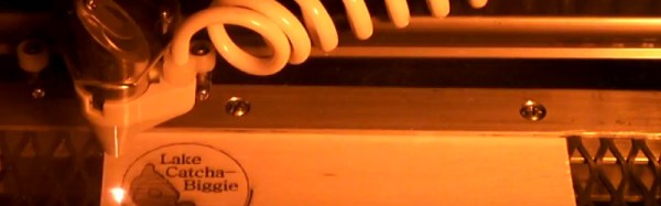
The relatively inexpensive K40 laser cutter/engraver machines from China have brought laser cutting to the masses, but they are not without their faults. Sure, they’re only powerful enough for the lightest cutting tasks, but on top of that, their bundled software is inflexible and disappointing. If your workshop or hackspace has one of these machines languishing in the corner, then the release of a new piece of software, K40 Whisperer from [Scorch], is an interesting and welcome development.
He tells us that the reverse engineering process required to understand the K40’s protocol was non-trivial, given that it does not use handy decimal numbers to issue commands. A spreadsheet was used to collate data packets and spot repeating patterns to analyse the inner workings. Feature-wise, the software reads SVG and DXF files, and can split SVGs by colour. It has a halftone algorithm for rendering grey scales, and cuts from the inside of each shape first to avoid pieces of work dropping out of the piece of material. Currently it works with the stock M2 Nano controller board and is available as a Windows download, though it can also be compiled for Linux distributions, or MacOS, and he is asking owners to test it with as many machines as possible to ensure compatibility with other boards.
He has posted a video of K40 Whisperer in action, which you can see below the break.
When you take an item with you on a camping trip and it fails, you are not normally in a position to replace it immediately, thus you have the choice of fixing it there and then, or doing without it. When his LED camping lantern failed, [Mark Smith] was in the lucky position of camping at a friend’s compound equipped with all the tools, so of course he set about fixing it. What he found shocked him metaphorically, but anyone who handles it while it is charging can expect the more literal variation.
The lamp was an LED lantern with built-in mains and solar chargers for its Ni-Cd battery pack, and a USB charger circuit that provided a 5 volt output for charging phones and the like. The problem [Mark] discovered was that the mains charger circuit did not have any mains isolation, being a simple capacitive voltage dropper feeding a rectifier. These circuits are very common because they are extremely cheap, and are perfectly safe when concealed within insulated mains-powered products with no external connections. In the case of [Mark]’s lantern though the USB charging socket provided that external connection, and thus access to a potential 120 VAC shock for anyone touching it while charging.
Plainly this lamp doesn’t conform to any of the required safety standards for mains-powered equipment, and we’re guessing that its design might have come about by an existing safe lamp being manufactured with an upgrade in the form of the USB charger. The write-up gives it a full examination, and includes a modification to safely charge it from a wall-wart or similar safe power supply. Definitely one to watch out for!
If you were wondering what the fault was with Mark’s lamp, it was those cheap NiCd batteries failing. He replaced them, but there are plenty of techniques to rejuvenate old NiCds, both backyard, and refined.
Ever on the lookout for creative applications for tech, [Andres Leon] built a solar powered battery system to keep his Christmas lights shining. It worked, but — pushing for innovation — it is now capable of so much more.
The shorthand of this system is two, 100 amp-hour, deep-cycle AGM batteries charged by four, 100 W solar panels mounted on an adjustable angle wood frame. Once back at the drawing board, however, [Leon] wanted to be able track real-time statistics of power collected, stored and discharged, and the ability to control it remotely. So, he introduced a Raspberry Pi running Raspbian Jessie Lite that publishes all the collected data to Home Assistant to be accessed and enable control of the system from the convenience of his smartphone. A pair of Arduino Deuemilanoves reporting to the Pi control a solid state relay powering a 12 V, 800 W DC-to-AC inverter and monitor a linear current sensor — although the latter still needs some tinkering. A in-depth video tour of the system follows after the break!
Badgelife is the celebration of independent hardware creators, working for months at a time to bring custom electronic badges to conferences around the world. This year at DEF CON, Badgelife is huge. It’s not just because this year was supposed to feature a non-electronic badge, and it’s not because the official badge imploded last month — Badgelife is all about people spending most of the year designing, and manufacturing hardware, culminating in one very special weekend.
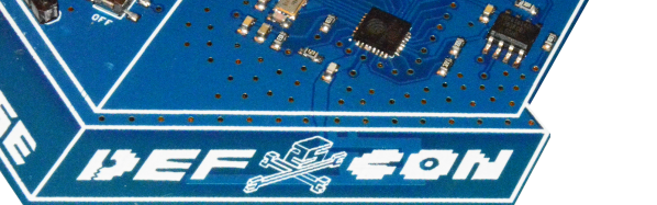
[Garrett] owns Hacker Warehouse, a store providing all kinds of neat hacker tools ranging from software-defined radios to lock pick sets to side channel analysis toolkits. This year, [Garrett] decided he wanted to branch out his business and get involved in a little bit of hardware creation. He’s been curious about this for some time and figured a limited edition DEF CON badge made sense. What he wound up with is a beautiful little badge with games, blinkies, graphics, and potential to cause a lot of wireless mischief.
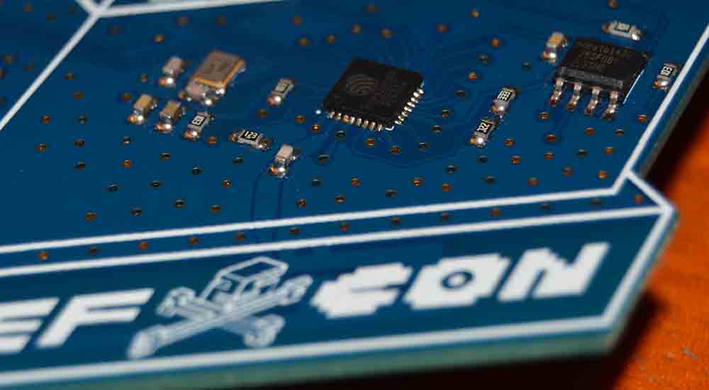
Would you look at that. RF design on an independent badge.
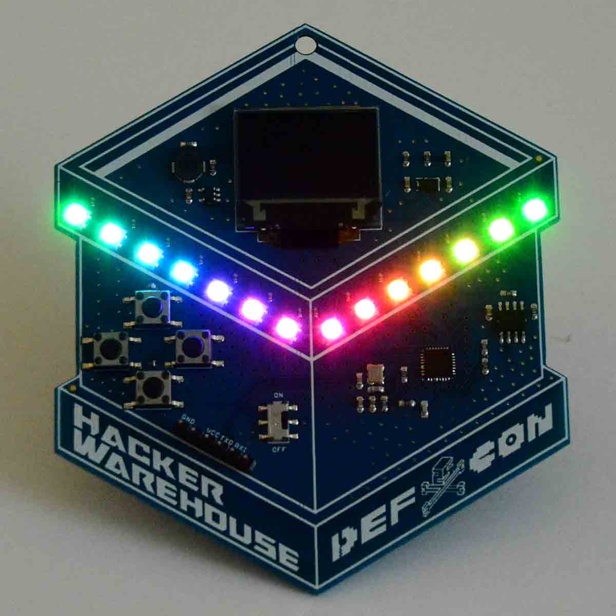
The design of the Hacker Warehouse badge is surprisingly simple compared to the Bender Badges and puzzling crypto badges that are also part of this year’s Badgelife hardware celebration. On board is an ESP8266 with a custom PCB implementation that includes a larger Flash chip. The other side of the board is loaded up with four tact switches in a D-pad arrangement. On top is a 96 x 64 pixel full-color OLED display, and blinkies are provided by fourteen mini WS2812 RGB LEDs. Power is provided by two AA cells and what looks to be a nice fancy switching regulator. This is real hardware, not just a few modules thrown together with a bunch of LEDs.
Oh, what wireless fun
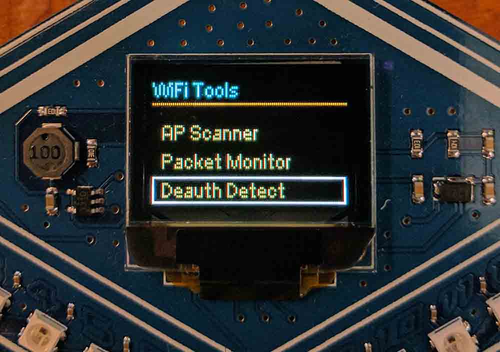
This badge is built around the ESP8266, a very interesting WiFi-enabled microcontroller that has more features than it should. [Garrett] is using the ESP as a WiFi scanner of sorts, allowing anyone with this badge to monitor WiFi channels, APs, packets, and — this is important — deauth packets.
Over the last year, there have been a number of projects around the Internet that take an ESP8266 and spew deauthorization frames into the spectrum. These frames cause a WiFi client to stop using an access point, and basically shuts down all the WiFi in an area. It’s well documented, and people have been doing it for years, but the ESP8266 makes deauth attacks so very, very easy. We’re going to see a lot of deauth frames this year at DEF CON, and the Hacker Warehouse badge will be able to detect them. It can also generate these frames, but that capability is locked for now.
Blinking and glowing
An electronic conference badge isn’t cool unless it has obnoxiously bright and glowy LEDs, and the Hacker Warehouse badge is very cool.
Onboard the Hacker Warehouse badge are 14 RGB LEDs, programmed with 46 different patterns that are certainly bright enough to annoy someone. This is what you need for a badge, and it’s beautiful.
This is a truly fantastic badge that’s also a great development board for the ESP8266. Everything you need for portable WiFi gaming fun is already there — you have blinky LEDs, an OLED, what seems to be a fairly nice power supply, and enough buttons to do something interesting. All you need to do to program this badge is attach a USB to serial adapter to the pre-populated header and you really have something. It’s a great badge, and we can’t wait to see the hacks for this great piece of hardware next week at DEF CON.