[Richard Hawthorn] sent us in this interesting fail, complete with an attempted (and yet failed) clever solution. We love learning through other people’s mistakes, so we’re passing it on to you.
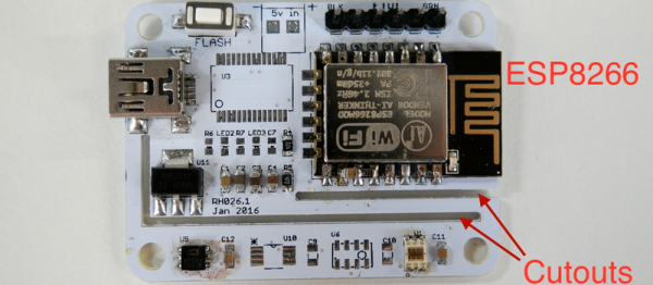
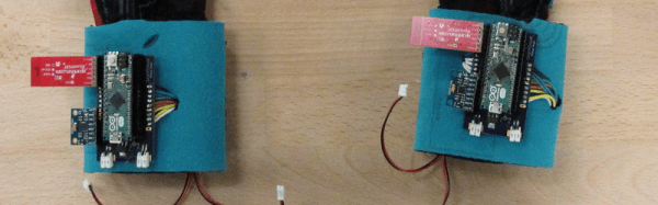
First the obvious-in-retrospect fail. [Richard] built a board with a temperature sensor and an ESP8266 module to report the temperature to the Interwebs. If you’ve ever put your finger on an ESP8266 module when it’s really working, you’ll know what went wrong here: the ESP8266 heated up the board and gave a high reading on the temperature sensor.
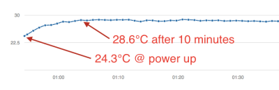 Next came the clever bit. [Richard] put cutouts into the board to hopefully stop the flow of heat from the ESP8266 module to the temperature sensor. Again, he found that the board heats up by around four degrees Celcius or nine degrees Farenheit. That’s a horrible result in any units.
What to do? [Richard’s] first ideas are to keep hammering on the thermal isolation, by maybe redoing the board again or adding a heatsink. Maybe a daughterboard for the thermal sensor? We can’t see the board design in enough detail, but we suspect that a flood ground plane may be partly to blame. Try running thin traces only to the temperature section?
[Richard]’s third suggestion is to put the ESP into sleep mode between updates to reduce waste heat and power consumption. He should be doing this anyway, in our opinion, and if it prevents scrapping the boards, so much the better. “Fix it in software!” is the hardware guy’s motto.
But we’ll put the question to you electronics-design backseat drivers loyal Hackaday readers. Have you ever noticed this effect with board-mounted temperature sensors? How did you / would you get around it?
 Fail of the Week is a Hackaday column which celebrates failure as a learning tool. Help keep the fun rolling by writing about your own failures and sending us a link to the story — or sending in links to fail write ups you find in your Internet travels.
 In his latest build he has produced