In the first article about measurement systems we looked at sensors as a way to bring data into a measurement system. I explained that a sensor measures physical quantities which are turned into a voltage with a variable conversion element such as a resistor bridge. There will always be noise in any system, and an operational amplifier (op-amp) can be used to remove some of that noise. The example we considered used an op-amp in a differential configuration that removes any disturbance signal that is common to both inputs of the op-amp.
But that single application of an op-amp is just skimming the surface of the process of bringing a real-world measurement of a physical quantity into a digital system. Often, you’ll need to do more work on the signal before it’s ready for sampling with a digital-to-analog converter. Signal conditioning with amplifiers is a deep and rich topic, so let me make it clear that that this article will not cover every aspect of designing and implementing a measurement system. Instead, I’m aiming to get you started without getting too technical and math-y. Let’s just relax and ponder amplifiers without getting lost in detail. Doesn’t that sound nice?
Continue reading “Beyond Measure: Instrumentation Amplifiers”
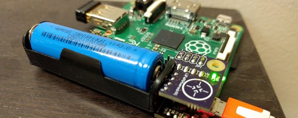
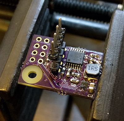 [Patrick]’s Raspberry Pi UPS isn’t just a battery and charge controller attached to the power rails; this board has a microcontroller that has full control over when the Pi wakes up, when the Pi goes to sleep, and can put the Pi into a clean shutdown, even in headless mode. SD cards around the world rejoiced.